MTS 793 Controller Hardware FlexTest GT Controller Connections
79
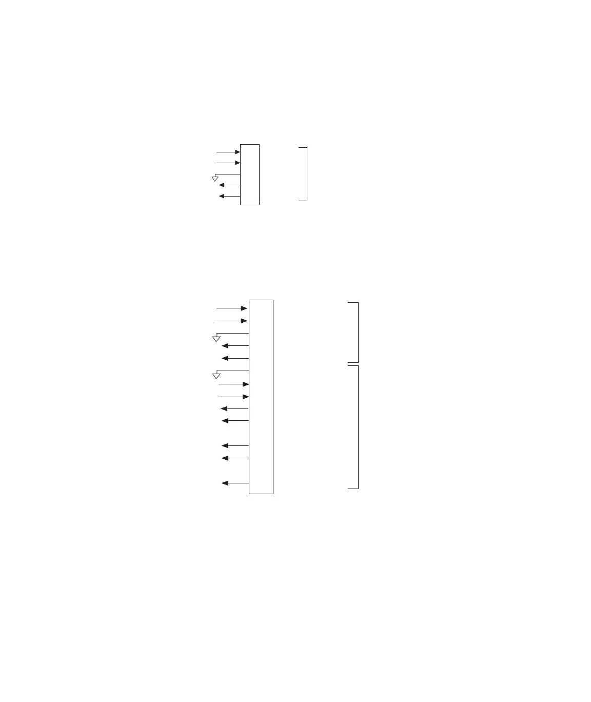
Excitation and feedback signals are passed through to the transducer,
as shown.
If purchased as an option, a transducer ID module is located in the
transducer cable. Excitation and feedback signals are passed through
to the transducer.
J4 - J7
To/From
Conditioner
To/From
Transducer
1
2
3
4
5
+ Excitation
- Excitation
Guard
+ Feedback
- Feedback
1
2
3
4
5
6
8
11
14
10
9
12
13
14
15
J4 - J7
To/From
Conditioner
To/From
Transducer
ID Module
+ Excitation
- Excitation
Guard
+ Feedback
- Feedback
Signal Common
Clock
Data to Sensor ID
Data from Sensor ID
+ Excitation Sense
Remote Calibration
+ Feedback Return
- Feedback Return
- Excitation Sense
To/From
Transducer
Artisan Technology Group - Quality Instrumentation ... Guaranteed | (888) 88-SOURCE | www.artisantg.com