Installation
36 Series 505G2 SilentFlo™ Hydraulic Power Unit
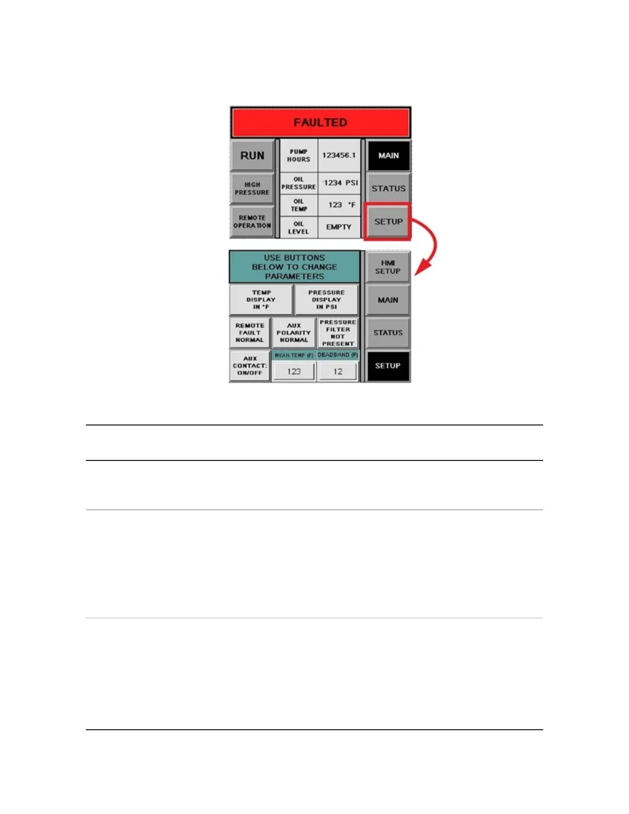
Setup HMI (human-machine interface) screen.
5. The following table describes the pushbuttons and indicators on the Setup screen.
Name and
Location
Description
Use Buttons Below
To Change
Parameters
Indicator - blue-green: Provides instruction for the setup screen.
Remote Fault
Normal/Remote
Fault Reverse
Pushbutton /Indicator. The HPU generates fault signals for remote
monitoring. This button is used to define the polarity of the output signal.
Remote Fault Normal - gray: The remote fault signal is active high
meaning the fault contact is closed when a fault is present.
Remote Fault Normal - black: The remote fault signal is active low
meaning the fault contact is open when a fault is present.
Aux Contact:
On/Off/Temp
Aux Polarity
Normal/Reverse
Pushbuttons /Indicators.
Aux Contact: On/Off - gray
Aux Contact: Temp - black
Aux Polarity Normal - gray
Aux Polarity Reverse - black
 Loading...