7.5 Valve Drive
7.5.1 Valve clearance – Check and adjustment
Preconditions
☑Engine is stopped and starting disabled.
☑Engine coolant temperature is max. 40 °C.
☑Valves are closed.
Special tools, Material, Spare parts
Designation / Use Part No. Qty.
Feeler gage
Y4345893 1
Engine barring gear
F6783914 1
Ratchet
F30006212 1
Double-head box wrench
F30002800 1
Offset screwdriver
F30002816 1
Socket wrench
F30030450 1
Torque wrench, 10-60 Nm
F30510423 1
Measuring device
Y4345888 1
Preparatory steps
1. Remove air filter (→ Page 101).
2. Remove cylinder head cover (→ Page 85).
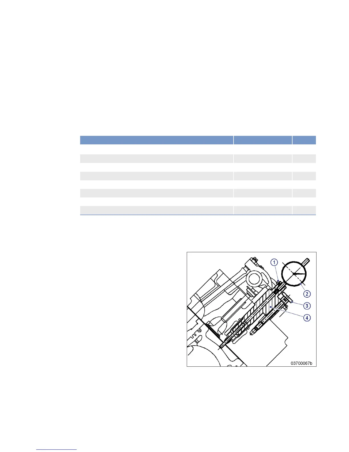
Positioning A1 piston at TDC
Note: With cylinder head and valve gear installed.
1. Install dial gage (2) under preload in meas-
uring device (4) and clamp with screw (1).
2. Install measuring device (4) in cylinder
head and secure using knurled-head
screw (3).
3. Zero dial gage (2).
4. Turn engine using barring gear until piston
A1 reaches firing TDC.
Result: The piston is at firing TDC when both rock-
er arms are unloaded, i.e. have clearance.
Checking valve clearance at two crankshaft positions
1. Check TDC position of piston in cylinder A1:
• If the rocker arms are unloaded on cylinder A1, the piston is in firing TDC.
• If the rocker arms are loaded on cylinder A1, the piston is in overlap TDC.
2. Check valve clearance with cold engine:
• Inlet (I) = 0.3 mm;
• Exhaust (X) = 0.4 mm.
M015590/06E 2014-03
| Task Description | 83
TIM-ID: 0000050015 - 002



 To Next Page