1. Instrumentation
The schematics of the instrument dashboards 80-3805010-Д1 and 826-3805010 are giv-
en in the section “Appendix”.
The instrumentation includes:
- the combination meter (Р2) with sensors;
- the electric tachospeedometer (Р1) with the control board (А3) and sensors;
- the electric light and audible alarms combined into two pilot lamp units (HG1 and HG2)
in the instrument dashboard 80-3805010-Д1 or into the pilot lamp unit and combination
meter in the instrument dashboard 826-3805010.
To switch on the instruments, turn the starter and instrumentation switch to the “I” posi-
tion. Then the voltage will be applied to the terminal “K3” of the switch, then to the relay
for power supply of the instruments, to the fuse (F2) of the unit and further – to the units
(HG1 and HG2), tachospeedometer (Р1), alarm device (НА2), combination meter (Р1)
and speed sensors (BV1 and BV2).
The instrument pointers shall move to the zero position or to the position corresponding
to the true value of the parameter controlled by the system at the moment.
In case of deviation of readings of the instruments from their true values, detect the
cause of the fault following the recommendations below.
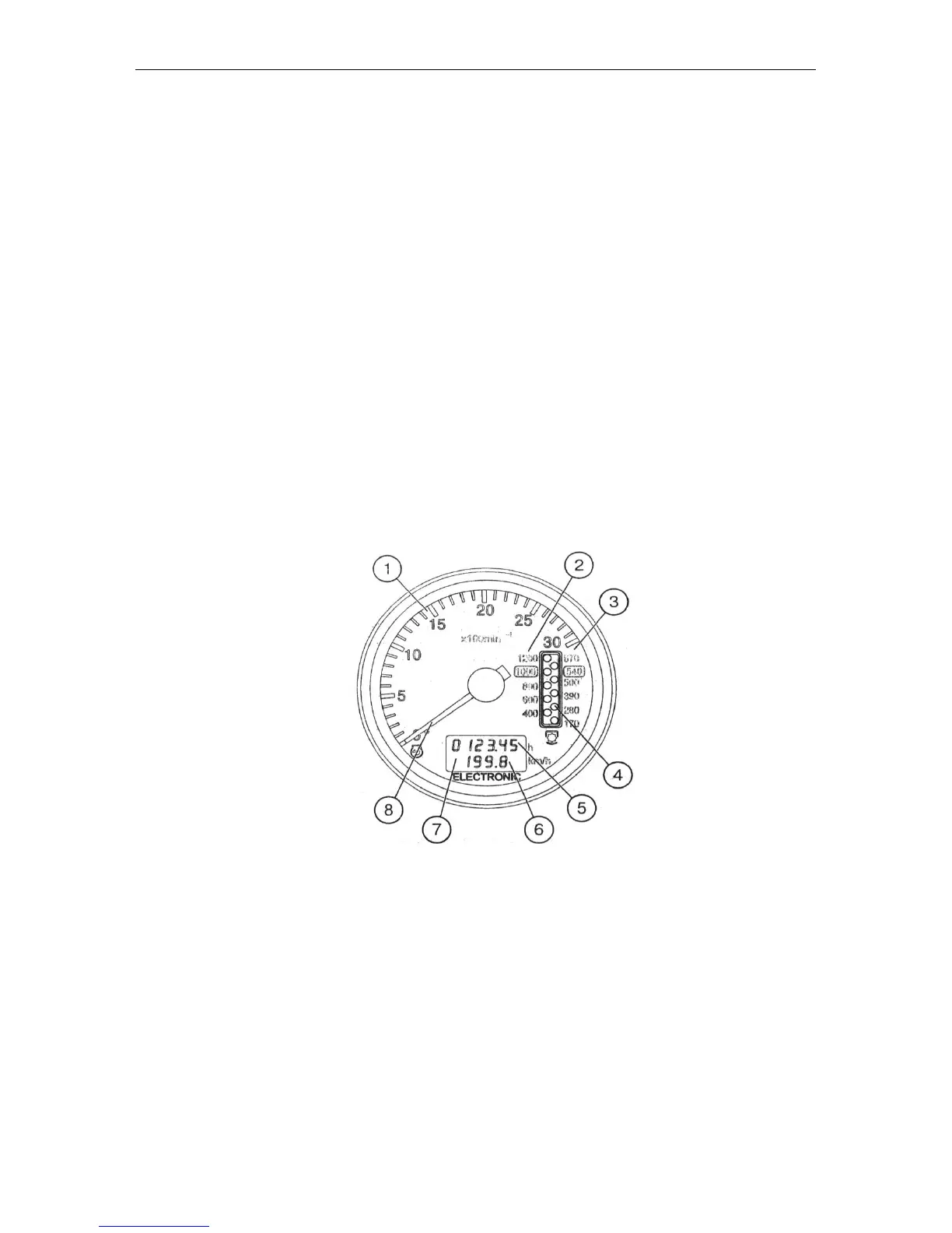
1.1. Tachospeedometer АР70.3813 (Fig. 1)
Fig. 1. Tachospeedometer (Р1):
1 . Engine crankshaft rotational speed scale, rpm.
2 . PTO II rotational speed scale –1000 rpm.
3 . PTO I rotational speed scale –540 rpm.
4 . PTO rotational speed display (LED).
5 . Engine running hours indication, h.
6 . Tractor speed indication, km/h.
7 . Display of engine running hours and tractor speed, km/h.
8 . Pointer indicator of the engine crankshaft speed (LCD).
The electric tachospeedometer АР703813 installed in the dashboard operates as follows:
• On setting the starter and instrument switch is put to position I when the tractor is
stopped, the display (7) shows the engine running hours (5);