1.6. Combined indicator КД 8083
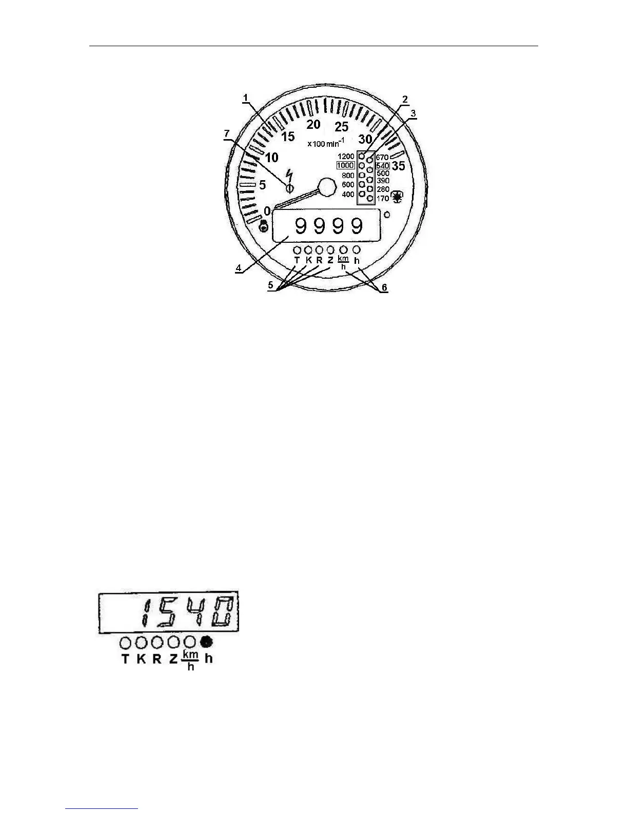
Fig. 4. Tachospeedometer (Р1):
1 – Engine rotational speed indicator (pointer indicator).
2 – PTO 1000 rotational speed scale (opposite to the respective value of the PTO ro-
tational speed).
3 – PTO 540 rotational speed scale (opposite to the respective value of the PTO rota-
tional speed).
4 – Five-digit indicator.
5 – LED’s lighting up in the mode of programming the coefficients “K”, “R” and “Z”
(opposite to the respective LED).
6 – LED’s lighting up in the mode of display of the motion speed “km/h” and total en-
gine running time “h” (opposite to the respective LED).
7 – Alarm of the overvoltage in the tractor on-board power system (red) operates, if
the voltage exceeds 18.5 V.
In this case the instrument is switched off because the protective device operates. Should the voltage
drop down to 16.5 V, the indicator returns to the operating state and the overvoltage indicator goes out.
Indicator operating procedure
On switching on the power supply, the indicator is switched to the main operating
mode. In case of absence of signals from the speed sensors the digital indicator (4)
shows the reading of the total engine running time and the LED located next to the sym-
bol “h” lights up.
Total engine running time:
Appearance of the pulses from the speed sensors at the input of the pulse indicator
causes the switching-on to the motion speed indication mode. Then the measured
calculated speed reading is shown on the digital indicator and the LED located next to
the symbol “km/h” lights up.
The calculated motion speed (km/h).