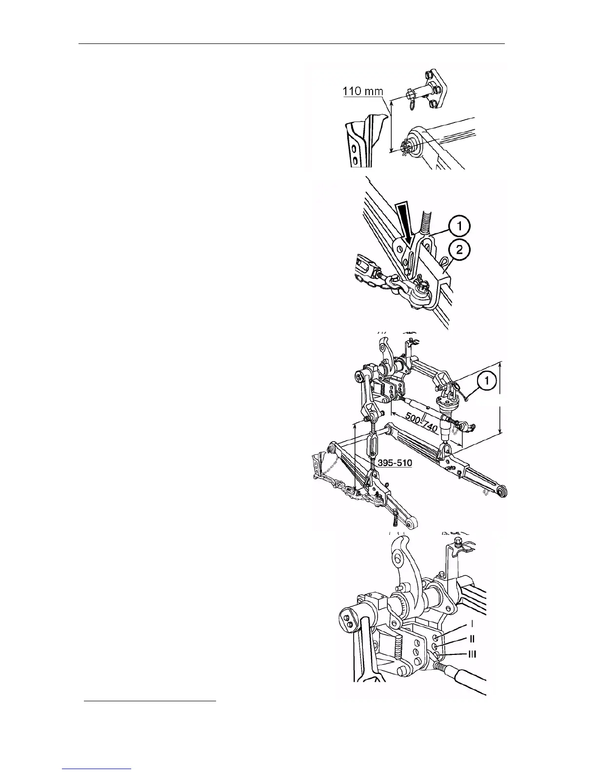
To increase the clearance when cultivat -
ing the high-stem crops, install the front
e n ds of the lower rods onto the addition -
al hanger axles located at the distance of
110 mm above the lower rod axis. To im-
itate field profile crosswise when operat -
ing wide-cut implements, connect the
angle braces (1) with lower rods (2) via
longitudinal grooves.
IMPORTANT! To avoid the damage of
the angle brace, the angle brace fork
grooves shall be behind the aperture.
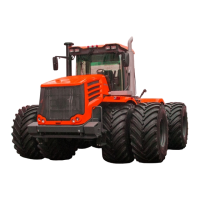
Upper rod and angle braces
The upper rod length is adjusted within
500…740 mm. The length of the right ad -
justable angle brace can be adjusted
within 425…520 mm by rotating the h a n -
dle (1). When being shipped from the
f a ctory, the right angle brace length is set
to the standard value of 475 mm. When
the tractor is shipped from the factory,
the left (non adjustable) angle brace
length is set to standard 475 mm.
During operation, the left angle brace
length can be changed within 395…510
mm, depending on the standard equip -
ment of the tractor and type of unitized
machines and implements.
IMPORTANT! Make adjustment of the
implement laterally with the right angle
brace only.
Depending on the tillage depth and soil na -
ture, install upper rod to one of the three
*
positions:
I – light soils and small tillage depth at
power control;
I I – medium soils and medium tillage
depth at power control;
I I I – heavy soils at large tillage depth, as
well as at position control or without
power governor.