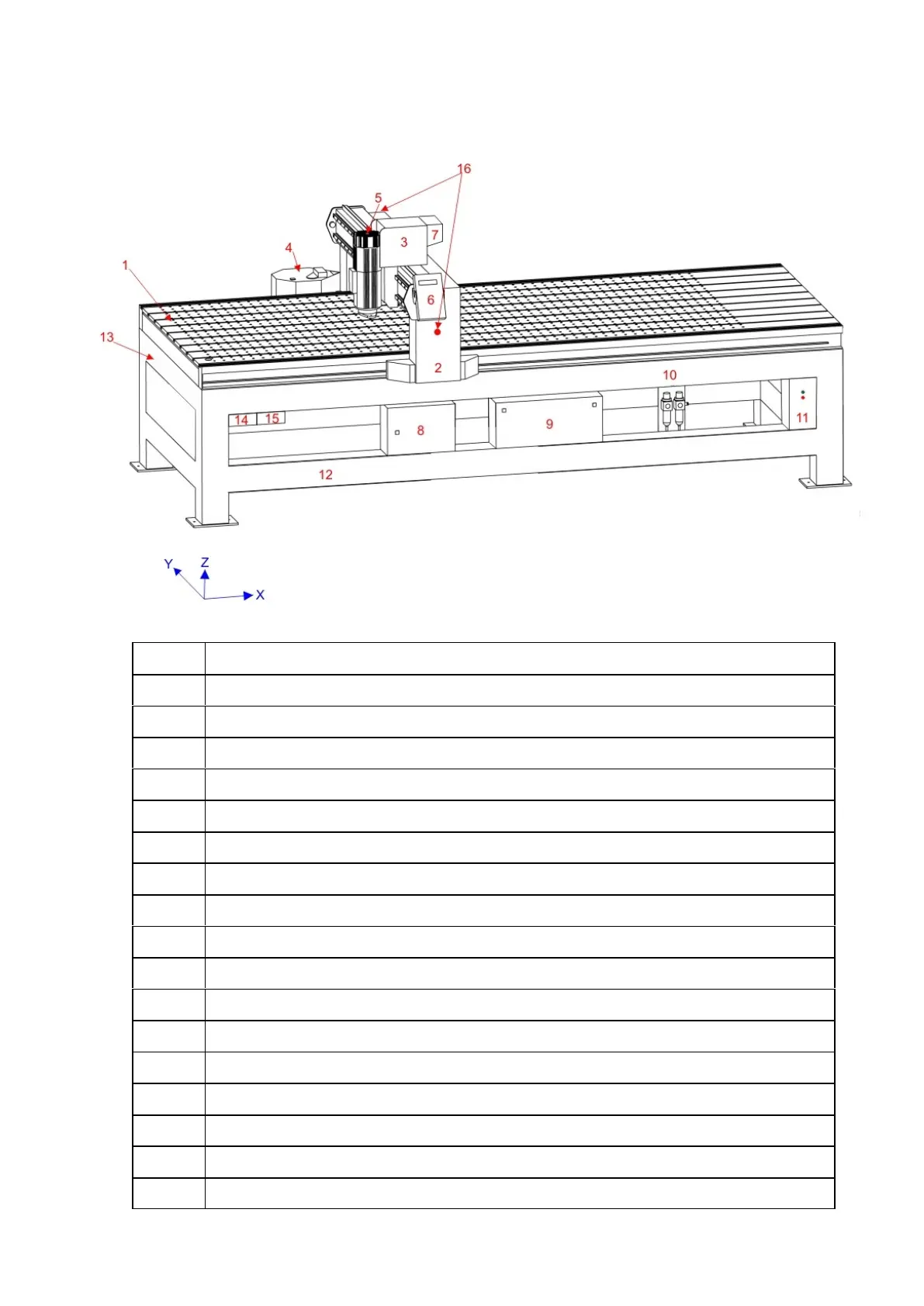
Machine Component Identification
The following diagram and table indicates the location of major components of the machine. There
may be variations depending on individual size, configuration and options fitted.
Item Description Items marked * are optional and may not be present on all machines
1 Machine bed. Aluminium vacuum hold down table or t-slot table
2 Travelling steel gantry. Contains X axis drives
3 Machine head. Contains Y and Z axis drives
4 Travelling rotary tool changer*
5 Location of cutting spindle/s*, knife head/s*, camera*
5 Location of Air assist head attachment*
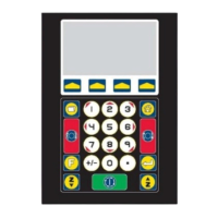
6 Operator’s sub console unit
7 Mist sprayer attachment*
8 Inverter enclosure - Danger High Voltage
9 A2MC controller enclosure - Danger High Voltage
10 Micro air filter inlet and distribution
11 Power Box Master On/Off control for machine - Danger High Voltage
12 Machine frame
13 Linear tool changer*
14 Machine air supply, tool change and vacuum pressure gauges*
15 Additional switches for dust collectors, vacuum pumps, other ancillary devices*
16
Emergency stop buttons, operator’s and off side of gantry