PAGE 20 — MAYCO LS450 CONCRETE PUMP • OPERATION MANUAL — REV. #2 (02/23/21)
GENERAL INFORMATION
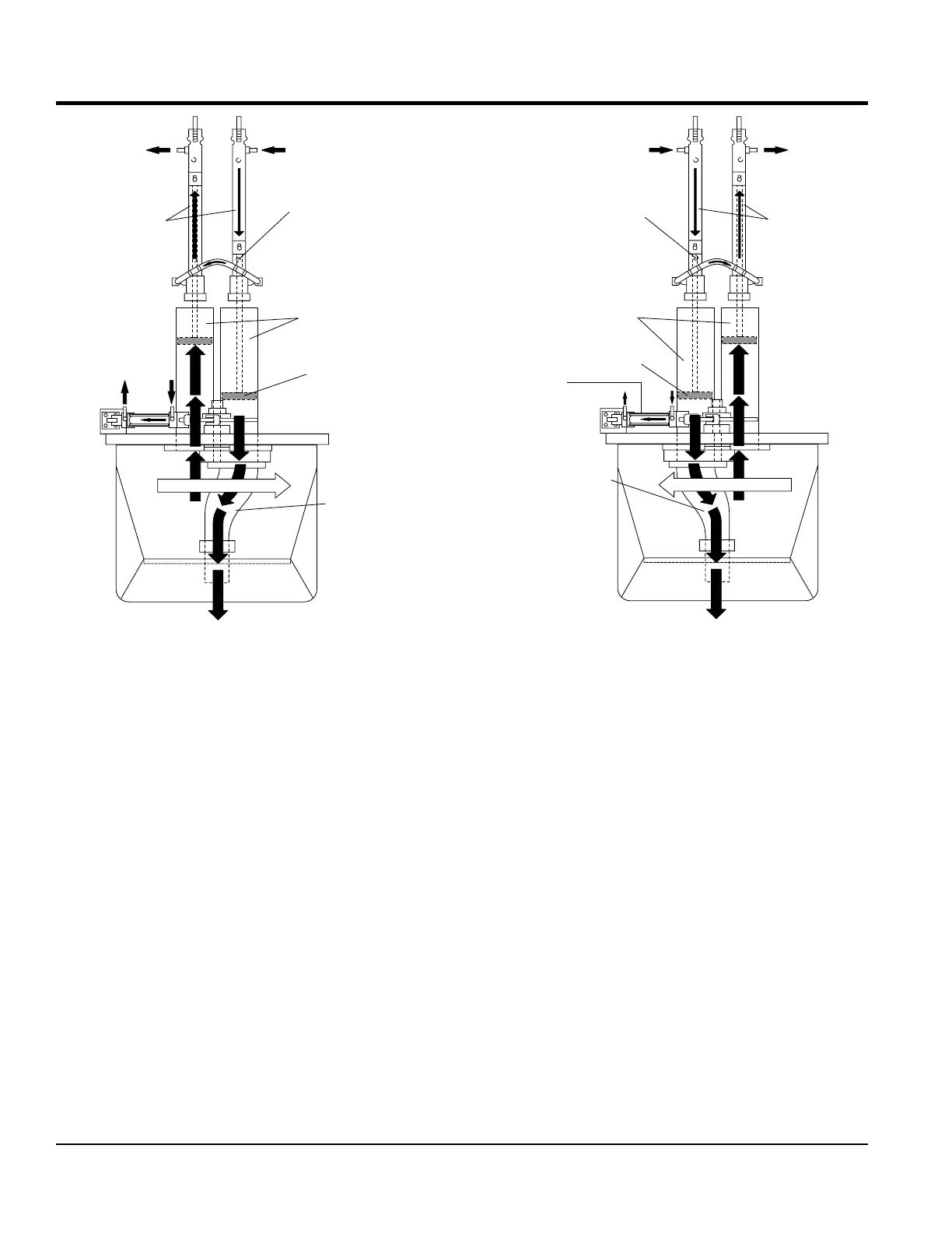
Figure 3. Pumping Cycle 1
In the first cycle (Figure 3), hydraulic pressure is applied to
cylinder (B) causing the hydraulic piston, which is connected
to the concrete piston and piston cup, to discharge concrete
into the delivery line.
As one cylinder is discharging concrete, the hydraulic
oil from the rod side (B) of the drive cylinders is being
transferred through the slave circuit, causing the opposite
cylinder (A) to move back on the suction stroke, filling the
cylinder with concrete.
The shuttle tube is sequenced to pivot to each concrete
cylinder as the drive cylinders stroke to push concrete.
TO TANK
HIGH PRESSURE
OIL FROM PUMP
PROXIMITY
SWITCH
HYDRAULIC
CYLINDERS
PISTON
CUP
CONCRETE
CYLINDERS
SHUTTLE
SLAVE
OIL
SHUTTLE TUBE MOTION
A
B
Figure 4. Pumping Cycle 2
As the second cycling sequence begins (Figure 4), the
shuttle tube pivots to the opposite cylinder (A).
The hydraulic piston passes under the proximity switch
and sends pressure to the piston, causing it to stroke
and discharge concrete into the delivery line. Hydraulic
oil is transferred through the slave circuit to cylinder (B),
causing it to start a suction stroke, refilling it with concrete.
The pumping sequence then repeats for the duration of
the operation.
TO T
HIGH PRESSURE
OILFROM PUMP
PROXIMITY
SWITCH
HYDRAULIC
CYLINDERS
PISTON
CUP
CONCRETE
CYLINDERS
SHUTTLE TUBE
SLAVE
OIL
SHUTTLE TUBE MOTION
A
B
B