MAYCO LS450 CONCRETE PUMP • OPERATION MANUAL — REV. #2 (02/23/21) — PAGE 51
DO NOT allow the cups to become so worn that they begin
to pass lubrication into the material cylinders.
If the liquid level of the lubrication box becomes too low,
the rubber cups will severely deform due to excessive heat.
When it is time for replacement, both cylinder cups should
be replaced.
Cylinder Cup Replacement Procedure
1. Remove the two hydraulic hoses connected to the
remix motor. Plug the ports with fittings (not provided)
to prevent hydraulic hose leakage.
2. Remove the hopper discharge nipple and loosen the
sleeve seal. Inspect and replace if wear is excessive.
3. Remove the two tie rod nuts and the four eyebolt nuts
securing the hopper to the pump frame.
4. Using an approved lifting device, remove the hopper
using extreme care to not damage the hopper seal.
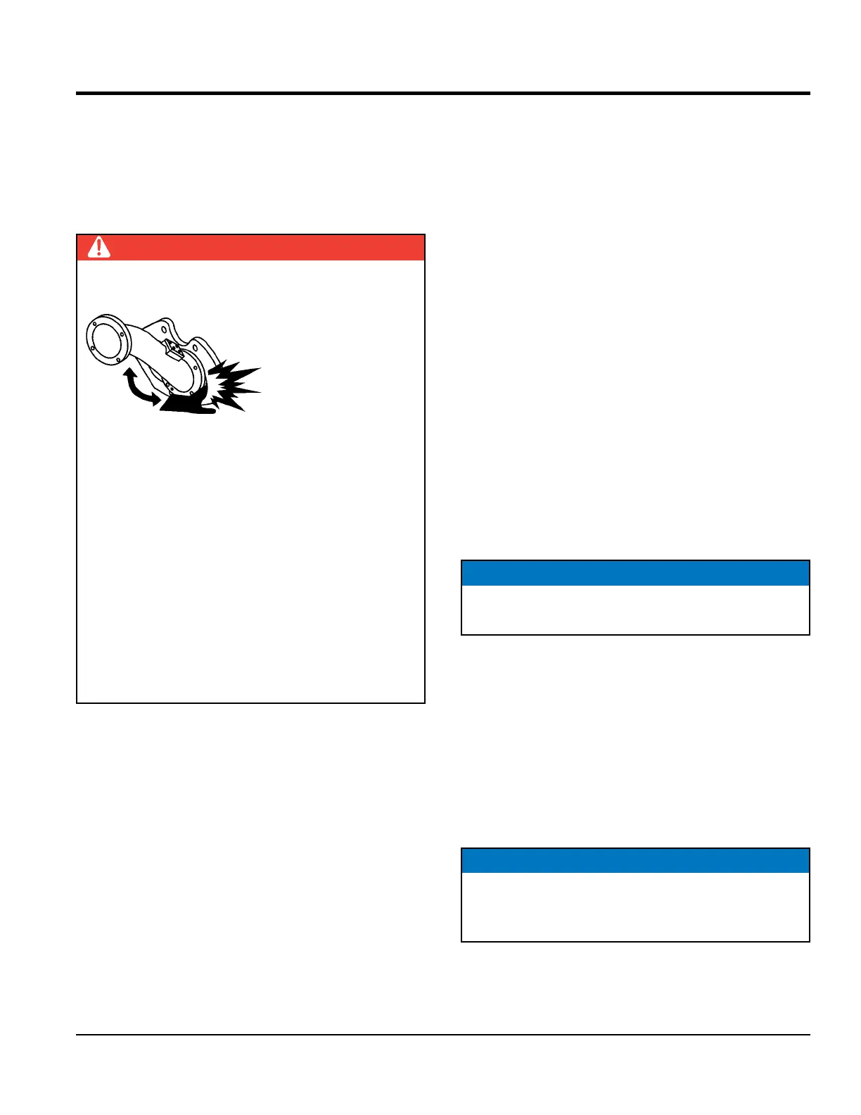
DANGER
AMPUTATION HAZARD
During routine
maintenance or
removal of material
blockage, you will be
required to put your
hand in the concrete
cylinders or near the
shuttle tube. You are at extreme risk of injury or
AMPUTATION if the engine is running or if pressure
is in the hydraulic system.
Prior to performing any maintenance on the pump,
follow described lockout/tagout procedures. Stop the
engine by turning off the ignition switch and remove
the starter key.
Place a DO NOT OPERATE tag over the switch and
disconnect the battery. The pressure reading on
the accumulator pressure gauge MUST read zero.
ALWAYS make sure the accumulator circuit pressure
reads zero prior to performing any maintenance on
the pump.
5. Start the engine and turn on the pressure test switch.
Cycle the pump in reverse until the hydraulic system
obtains maximum pressure, then turn the pump and
engine off.
6. Remove the ignition key and disconnect the battery.
Think SAFETY! Check the hydraulic gauges on the
panel and make sure the accumulator pressure gauge
reads zero. One piston should be in the fully discharged
position at the end of the concrete cylinder.
7. Remove the three 3/8-16 × 3" bolts from the piston.
Remove the front faceplate.
8. Install two of the 3/8-16 × 3" bolts back into the piston,
but DO NOT tighten. Use the two bolts as leverage to
remove the rubber piston cup and rear components.
9. Obtain two 3/8-16 × 7" full thread studs. These studs
will be used to assist in assembly alignment. Insert the
two studs into the piston adapter. Coat the concrete
cylinder with grease.
10. Install the O-ring around the oiler plate. Install the
plate into the concrete cylinder utilizing the studs for
alignment.
11. Install the felt holder over the oiler plate. Install the felt
ring into the felt holder. Install the bronze ring.
12. Using silicon sealant, place a small bead of sealant
material on the front of the rubber piston cup and the
rear of the face plate. Install over the alignment studs
and into the concrete cylinders.
13. Insert one 3/8-16 × 3" bolt into the open bolt hole.
Remove the alignment studs one at a time and install
the remaining 3/8-16 × 3" bolts.
NOTICE
The felt ring must be saturated with 30-weight oil prior
to installation.
NOTICE
Before installing the 3/8" bolts, coat the back of the bolt
heads with silicon sealant. Torque all three bolts equally
at 55 lbf·ft each.
MAINTENANCE