PAGE 52 — MAYCO LS450 CONCRETE PUMP • OPERATION MANUAL — REV. #2 (02/23/21)
Wear Plate and Cutting Ring Replacement
Due to the swinging motion of the nun plate and the
abrasive nature of concrete, it is normal for the cutting
ring to wear on the side that shears through the concrete
inside the hopper.
If the wear ring and wear plate do not fully seat against each
other the concrete slurry will pump into the hopper. This
condition can be easily observed by the sudden change of
the level of concrete inside the hopper during each stroke.
1. Remove the two hydraulic hoses connected to the
remix motor. Plug the ports with fittings (not provided)
to prevent hydraulic hose leakage.
2. Remove the hopper discharge nipple and loosen the
sleeve seal. Inspect and replace if wear is excessive.
3. Remove the two tie rod nuts and the four eyebolt nuts
securing the hopper to the pump frame.
4. Using an approved lifting device, remove the hopper
using extreme care to not damage the hopper seal.
5. Remove the four 1/2" × 1-1/4" bolts securing the shuttle
tube to the nun plate and remove the shuttle tube.
6. Using two small pry bars, remove the rubber energizer
ring, steel insert ring, and wear ring.
7. Clean out all concrete buildup in and around the nun
plate area with a wire brush.
8. Inspect the wear components for indications of wear.
The wear plate has two wear surfaces.
NOTICE
The energizer ring and wear ring will normally have
concrete contamination holding them in position. It will
be necessary to chip some of the concrete loose to
better expose the energizer ring.
MAINTENANCE
Wear Plate Installation
1. Install the two cylinder O-rings.
2. Using silicon sealant, coat the circumference of the
concrete cylinders, the back of the wear plate, and
around the 5 bolt holes.
3. Install the wear plate and the 5 bolts. The bolts must
all be equally snugged and tightened to 100 lbf·ft each.
Wear Ring Installation
1. Install the wear ring into the nun plate.
2. Install the steel insert ring inside the rubber energizer
ring.
3. Install the energizer ring assembly into the nun plate.
4. Reassemble the machine by reversing steps 1–5 of
the Wear Plate and Cutting Ring Replacement
procedure.
HEAT EXCHANGER COOLING FAN
This section is intended to make sure the cooling fan is
working properly. Under normal conditions the fan should
be running any time the engine is turned on.
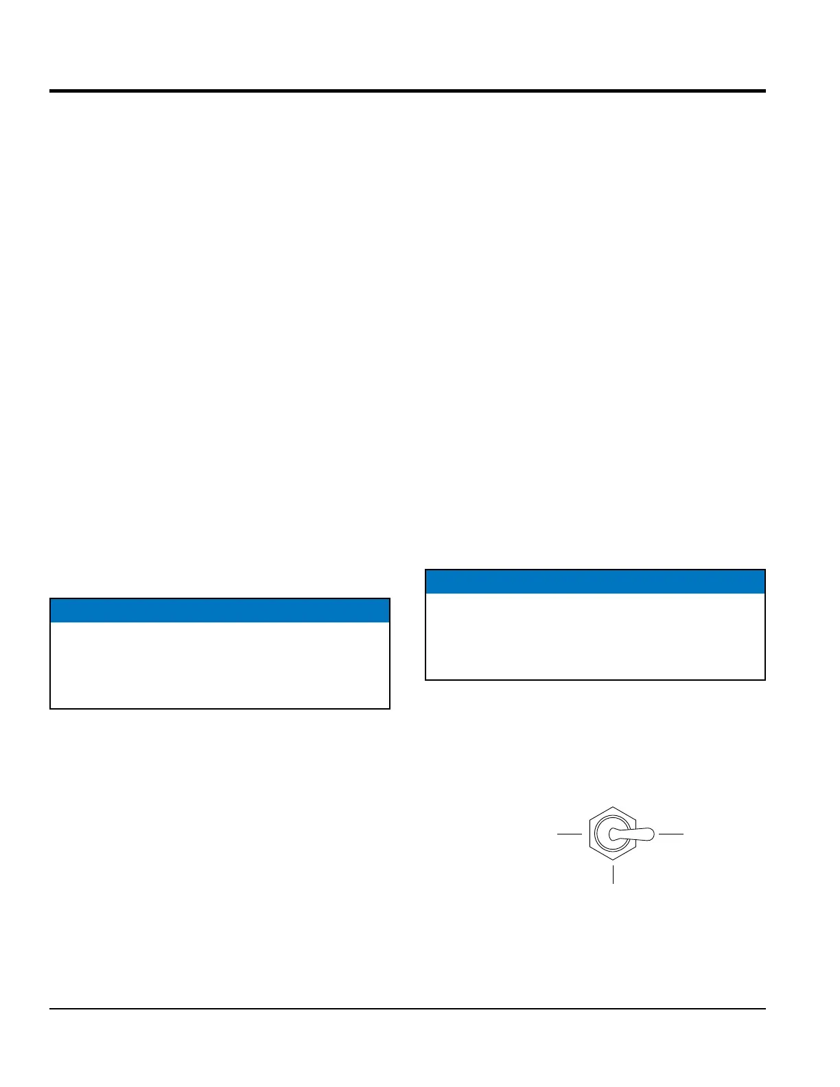
PRESSURE TEST
1. To determine the pressure of the hydraulic system,
set the cylinder stroke control switch (Figure 59) to
the JOG position.
Figure 59. Cylinder Stroke Control Switch (JOG)
NOTICE
If the hydraulic oil temperature exceeds 170°F (77°C),
shut down the pump. DO NOT continue to operate
the pump. Failure to shut down the pump will result in
severe damage to the pump.
OMATIC
CENTER
OFF