Do you have a question about the MULTISPAN CT-1000 and is the answer not in the manual?
Details on CT-1000, CT-2000, CT-3000, CT-5000 models including dimensions, display, input, and supply.
Details wiring and terminal connections for the CT-1000 model.
Details wiring and terminal connections for the CT-2000 model.
Details wiring and terminal connections for the CT-3000 model.
Details wiring and terminal connections for the CT-5000 model.
Guidelines to prevent electric shock and reduce electromagnetic interference during installation and operation.
Instructions for safe and proper installation of the equipment in control panels.
Guidance on panel cutout dimensions and fitting procedures for various models.
Instructions for cleaning the equipment and precautions regarding fusible resistors.
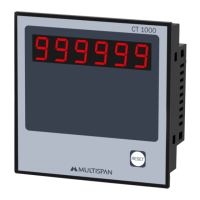
The device described in this manual is a Count Totaliser, designed to measure and display counts. It is available in several models: CT-1000, CT-2000, CT-3000, and CT-5000, each offering similar core functionality with variations in form factor and specific connection options. The primary function of these totalisers is to count events, providing a clear digital readout of the accumulated total.
The Count Totaliser operates by receiving input signals from various sources and incrementing an internal counter. The displayed value represents the total number of events detected since the last reset. The device is capable of counting from 0 up to 999,999, making it suitable for a wide range of industrial and commercial applications where event counting is required.
Input signals can originate from several types of sensors, including NPN/PNP Proximity Switches, Micro Switches, 230V AC Pulse sources, or Encoders. This versatility allows the totaliser to be integrated into diverse systems, such as production lines for counting items, machinery for tracking cycles, or access control systems for monitoring entries. The device's ability to accept both NPN and PNP proximity switch inputs further enhances its compatibility with different sensor types commonly found in automation environments.
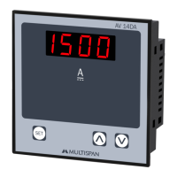
The display on all models is a single, multi-digit, 7-segment Red LED display, ensuring high visibility of the count even in varying lighting conditions. The size of the display digits varies slightly between models, but the fundamental principle of a clear, bright readout remains consistent.
Power supply requirements differ slightly across models. The CT-1000 and CT-5000 models typically operate on a 230V AC, 50Hz supply, while the CT-2000 and CT-3000 models offer a broader input voltage range of 100 to 270V AC, 50/60Hz. This flexibility in power input for certain models can be advantageous in regions with different electrical standards or where voltage fluctuations are common.
The totaliser is designed for built-in installation, meaning it typically becomes an integral part of a main control panel. This design ensures that once installed, the terminals are not easily accessible to the end-user, contributing to safety and a clean panel aesthetic.
The Count Totaliser is engineered for straightforward operation and integration. Its primary usage involves connecting appropriate sensors to its input terminals and providing the specified power supply. Once powered and connected, the device automatically begins counting events as detected by the sensors.
A crucial feature for practical use is the reset function. Each model includes a "RESET" button or a designated input for resetting the count to zero. This allows operators to clear the accumulated total and begin a new counting cycle as needed, for example, at the start of a new shift, batch, or production run.
The connection diagrams provided in the manual illustrate the wiring for each model, detailing connections for power (Line and Neutral), input signals, and in some cases, additional features like 230V AC Enable Pulse or +12V/+24V outputs for powering sensors. For instance, the CT-3000 and CT-5000 models provide a +12V or +24V output, respectively, which can be used to power NPN/PNP proximity switches, simplifying the wiring and reducing the need for external power supplies for the sensors.
Installation guidelines emphasize safety and proper setup. Users are instructed to ensure the power supply to the equipment is OFF during wiring to prevent electric shock. To minimize electromagnetic interference, it is recommended to use adequately rated and twisted wires for connections. The manual also specifies the minimum cross-section for power supply cables (1mm² or greater with at least 1.5kV insulation capacity) to ensure safe and reliable operation.
Mechanical installation involves preparing a panel cutout according to the dimensions provided for each model and then fitting the unit into the panel using the supplied clamps. It is important to ensure that the installed equipment is not exposed to heating sources, caustic vapors, oil steam, or other unwanted process by-products, as these can affect its performance and lifespan. When wiring the terminal block, users are advised to use specified crimp terminals and tighten screws to a torque within the range of 1.2 N.m to ensure secure connections.
The Count Totaliser is designed for minimal maintenance, focusing on ensuring continuous and reliable operation. The manual outlines a few key maintenance practices to prolong the life and accuracy of the device:
These maintenance guidelines are straightforward and aim to prevent common issues that could arise from environmental factors or improper cleaning, thereby contributing to the long-term reliability of the Count Totaliser. The emphasis on professional handling for certain internal components underscores the importance of not attempting unauthorized repairs.
| Continuity Test | Yes |
|---|---|
| Diode Test | Yes |
| Type | Digital Clamp Meter |
| Display | LCD |
| Resolution | 0.1A |
| Measurement Range | AC/DC Current: 0.1A-1000A, AC/DC Voltage: 0.1V-1000V, Resistance: 0.1Ω-2000Ω |
| Dimensions | 230mm x 75mm x 40mm |