EasyManua.ls Logo

MULTISPAN MFM 13-M1 User Manual

MULTISPAN MFM 13-M1
8 pages
To Next Page IconTo Next Page
Page #1 background imageLoading...
Page #1 background image
MFM 13-M1
MULTI FUNCTION METER
MECHANICAL INSTALLATION
TERMINAL CONNECTION
MFM 13-M1
LL
SET
ENT
VAF P/E
ENVIRONMENT CONDITION:
Relative Humidity
Protection Level
(AS Per Request)
Operating Temp.
0°C to 55°C
UP to 95% RH
(non-condensing)
IP-65 (Front side) As per IS/IEC
60529 : 2001
Class 0.5 (Standard)
ACCURACY:
AUXILIARY SUPPLY :
Supply voltage
Power consumption
(VA RATING)
Approx 4 VA @ 230V AC MAX
100 to 270V AC, 50/60Hz
TECHNICAL SPECIFICATION
SET/ENT,VAF,P/E, INC, DEC
4 Digit,3 Line 0.57" RED
Display
Key
DISPLAY & KEY :
Size
Panel Cutout
96 (H) x 96 (W) x 54 (D) mm
92 (H) x 92 (W) mm
DIMENSION :
POWER
ENERGY
Input Signal
PARAMETER SPECIFICATION
PT Primary
CT Secondary
PT Secondary
3Ø 3 Wire / 3Ø 4Wire / 1Ø 2Wire
CT Primary
up to 6000A (Programmable)
100V to 520kV (Programmable)
5 Amp/1 Amp selectable
100V to 520V (L-L) (Programmable)
KW Total
kW Per Phase
kWH Total
PF Avg. & Per Phase
kVA Total
kVAr Total
kVA Per Phase
kVAr Per Phase
Load hours
RPM
Frequency (Hz)
No load hours
0.000 - 9999 MW
0.000 - 9999 MW
000.000 - 999999999.999 kWh
000.000 - 999999999.999 kVAh
000.000 - 999999999.999 kVArh
0.100 - 1.000
0.000 - 9999 MVA
0.000 - 9999 MVAr
0.000 - 9999 MVA
0.000 - 9999 MVAr
45.00 - 60.00 Hz
9999.59 Hrs/Min.
9999.59 Hrs/Min.
3600 RPM @ 60 Hz & 2 pole
kVAh Total
kVArh Total
Outline Dimension (mm)
Panel Cutout
Dimension (mm)
92
92
96
96
54
3
RS-485 MODBUS
COMMUNICATION:
S1 S1 S1 S2S2S2
L1
L2
L3
L N
1 2 3 4
7
8
9
10
5
6
20
19 18
17
14
13
12
11
16 15
D+
MODBUS
D-
!
Made in India
100
270V AC
~
50/60 Hz
4VA
CAT III
VL1 VL2
VL3
N
Current: 30mA To 5A AC
Voltage (L-L) : 35-520V AC
(L-N) : 20-300V AC
Accuracy Class: 0.5
System: 1Ph-2W/3Ph-3W/3Ph-4W
Primary PT : 100V to 520KV
Secondary PT : 100V to 520V
Primary CT: Up to 6000A AC
Secondary CT: By 5A/1A AC
www.multispanindia.com
+
-
PULSE
O/P
Question and Answer IconNeed help?

Do you have a question about the MULTISPAN MFM 13-M1 and is the answer not in the manual?

MULTISPAN MFM 13-M1 Specifications

General IconGeneral
ModelMFM 13-M1
CategoryMeasuring Instruments
TypeMultifunction Meter
Frequency Range45-65 Hz
DisplayLCD
MountingPanel Mount
Measurement ParametersVoltage, Current, Power, Energy, Frequency, Power Factor
CommunicationModbus RTU
Dimensions96 x 96 mm

Summary

Technical Specifications

Parameter Specification

Details input signals, CT/PT ratios, frequency, load hours, and RPM for the meter.

Power Specifications

Specifies ranges for Total and Per Phase KW, KVA, and kVAr.

Energy Specifications

Details ranges for Total kWh, kVAh, and kVArh.

Mechanical Installation Details

Provides outline dimensions and panel cutout specifications.

Terminal Connection Diagram

Illustrates the terminal layout for wiring connections.

Auxiliary Supply & Communication

Specifies supply voltage, power consumption, and communication protocol (RS-485 Modbus).

Accuracy & Environmental Conditions

Details accuracy class, operating temperature, humidity, and protection level.

Display and Keypad

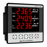
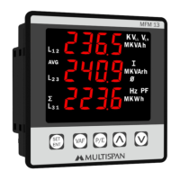
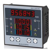
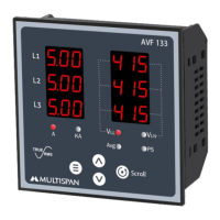
Describes the display type (4 Digit, 3 Line) and key functions.

Overall Dimensions

Specifies the overall size and panel cutout dimensions.

Key Operation and Setup

Key Operation Functions

Explains how to view VAF, Power & Energy pages, and scroll/hold pages.

Parameter Setting Mode

Details how to set, increment, decrement, and exit parameter settings.

Resolution Table

Lists pulse/kWh resolutions based on PT Ratio x CT Ratio.

Installation and Safety Guidelines

Mechanical Installation Guidelines

Provides guidelines for panel mounting, proximity, and terminal wiring.

Maintenance Procedures

Covers regular cleaning and restrictions on component replacement.

General Safety Precautions

Emphasizes following safety instructions and reading the manual.

Installation Requirements

Details installation requirements for built-in type units and circuit protection.

Warning Guidelines

Highlights risks of electric shock and guidelines for wiring and cable selection.

Basic Mode Operation

VAF Pages Navigation

Explains how to use the VAF key to navigate through Voltage, Current, and PF data.

Power & Energy Pages Navigation

Details using the P/E key to access Power and Energy measurements.

Parameter Setting Example

Demonstrates entering password and setting parameters like CT/PT and network selection.

Measurement Displays

VAF Data Display

Shows voltage, current, frequency, and power factor readings for different lines.

Power & Energy Data Display

Displays kW, kVA, kVAr per phase and total energy values.

Load Hour, RPM, and Reset Settings

Load Hour and RPM Display

Shows how to view Load Hour, No Load Hour, and RPM readings.

Load Hour & RPM Configuration

Details settings for Load Hour, Load Hour Percentage, RPM, and Pulse output.

Reset Settings

Explains how to reset all parameters or specific energy/hour counters.

Modbus Communication Settings

Modbus Configuration

Covers setting the Modbus address, baud rate, parity, and data type.

Modbus Register Map

Modbus Register Overview

Lists Modbus parameters, access types, and register data types.

Energy and Voltage Registers

Details registers for kWh, kVAh, kVArh, and various voltage measurements.

Current and Power Factor Registers

Covers registers for current values, power factor, and system frequency.

Power (kW) Registers

Lists registers for Line 1, 2, 3 kW values and Total kW.

Modbus Register Map (Continued)

Apparent Power (kVA) Registers

Details registers for Line 1, 2, 3 kVA values and Total kVA.

Reactive Power (kVAr) Registers

Covers registers for Line 1, 2, 3 kVAr values and Total kVAr.

Time and RPM Registers

Lists registers for Load Hour, No Load Hour, and RPM values.

Configuration and Reset Registers

Details registers for network selection, baud rate, parity, data type, and reset functions.

Related product manuals