Do you have a question about the MULTISPAN MS-1208A and is the answer not in the manual?
Input types, indication, and accuracy specifications.
Specifies the operational range of the device.
Details display type, key functions, and LED indicators.
Physical size and panel cutout dimensions.
Power supply voltage and consumption details.
Defines the accuracy class of the instrument.
Specifies the operating temperature range.
Specifies the relative humidity limit.
Details the protection rating of the unit.
Describes the function of various keys on the device.
Outlines operational steps and configuration.
Details the process for setting offset and correction factors.
Provides instructions for proper installation.
Safety warnings related to electrical shock and interference.
Precautions during installation to ensure safety.
Guidelines for maintaining the equipment.
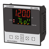
The Multispan MS-1208A is a versatile scanner designed for monitoring and displaying various input signals across multiple channels. This device serves as a central unit for observing and managing different process parameters, making it suitable for industrial control and monitoring applications.
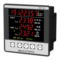
The MS-1208A functions primarily as a multi-channel scanner, capable of accepting a range of input signals, including 0-10V DC, 4-20mA DC, and 0-20mA DC. It features a dual-display system: an upper 4-digit 0.70” red LED display and a lower 4-digit 0.50” green LED display, allowing for clear and simultaneous visualization of process values and other relevant information. The device supports a broad input range from -999 to 9999, ensuring compatibility with a wide array of sensors and transducers.
A key feature of the MS-1208A is its ability to scan and display values from multiple channels sequentially or on demand. Users can configure the scan time, select the input type for each channel (e.g., 0-10V DC, 4-20mA DC), and choose to skip or unskip specific channels, providing flexibility in monitoring only the relevant parameters. The device also incorporates an offset and correction factor mechanism, allowing for precise calibration of each channel to compensate for sensor inaccuracies or system biases. This ensures that the displayed values are as accurate as possible, which is critical for reliable process control.
The scanner is equipped with a set of keys—SET, ENT, INC, DEC, LEFT, and RIGHT (Shift key)—that facilitate navigation through menus, parameter setting, and mode selection. These keys enable users to easily configure the device, adjust settings, and interact with the displayed data. The device's robust design and functionality make it an essential tool for applications requiring continuous monitoring of multiple process variables in a single, compact unit.
Operating the MS-1208A involves a straightforward procedure, starting with connecting all inputs as per the provided terminal diagram. To access the parameter menu, users press the SET key followed by the RIGHT Shift key. Within this menu, various configurations can be made, including setting the scan time, selecting the input type for each channel (e.g., 0-10V DC, 4-20mA DC), and enabling or disabling specific channels for monitoring.
For enhanced accuracy, the device allows for the addition of an offset to each channel. This is achieved by pressing the INC and DEC keys simultaneously for 5 seconds, after which the offset can be set as required. The device supports continuous scrolling or manual scrolling through channels by pressing the LEFT Shift key. In hold mode, the INC and DEC keys are used to select the next channel, providing granular control over the displayed information. Furthermore, users can set the low range, high range, and decimal point for each channel by pressing the SET and LEFT Shift keys together, offering comprehensive customization for different measurement scales.
The input selection process is intuitive: pressing the SET key after the RIGHT Shift key allows users to change parameters like scan time and input type for individual channels. The offset and correction factor settings are equally accessible, enabling users to fine-tune the device's readings. The mechanical design of the MS-1208A ensures easy installation. It requires a panel cutout with specific dimensions, and the unit is secured using clamps. Proper wiring involves using specified crimp terminals (M3.5 screws) and tightening them to a torque of 1.2 N.m. It is crucial to avoid connecting anything to unused terminals to prevent potential issues. The device is designed to operate within a temperature range of 0°C to 55°C and up to 95% relative humidity (non-condensing), with an IP-65 front-side protection level, making it suitable for various industrial environments.
Maintaining the MS-1208A is essential for ensuring its longevity and reliable performance. Regular cleaning of the equipment is recommended to prevent the blockage of ventilating parts. Users should clean the device with a clean, soft cloth. It is important to avoid using isopropyl alcohol or any other cleaning agents, as these could potentially damage the unit. The manual explicitly states that the fusible resistor must not be replaced by the operator, indicating that such tasks should be handled by qualified service personnel.
Safety precautions are paramount during maintenance and operation. All safety-related codifications, symbols, and instructions in the operating manual must be strictly followed. The equipment should not be handled in a manner not specified by the manufacturer, as this could impair the protection it provides. Prior to any installation or operation, users must read the complete instructions. To prevent the risk of electric shock, the power supply to the equipment must be turned OFF before performing any wiring arrangements. Terminals should not be touched while power is supplied.
To reduce electromagnetic interference, it is advised to use wires with adequate rating and twists of equal size, ensuring the shortest possible connection. Cables used for connecting to the power source should have a cross-section of 1mm or greater and insulation capacity of at least 1.5kV. Using a standard power supply cable for the instrument can also enhance anti-noise effects. As a built-in-type equipment, the MS-1208A typically becomes part of a main control panel, meaning its terminals are not accessible to the end-user after installation and internal wiring. It is crucial to prevent metal pieces, wire clippings, or fine metallic fillings from entering the product, as this could lead to safety hazards, including electrical shock. A circuit breaker or mains switch must be installed between the power source and the supply terminal to facilitate power ON/OFF, and it should be conveniently accessible to the operator. Finally, the instrument should be used and stored within the specified ambient temperature and humidity ranges to ensure optimal performance and durability.
| Type | Digital Multimeter |
|---|---|
| Diode Test | Yes |
| Continuity Test | Yes |
| DC Current Range | 0.1μA to 10A |
| Channels | 1 |
| Input Type | Single-ended |