Do you have a question about the MULTISPAN MPD-19N and is the answer not in the manual?
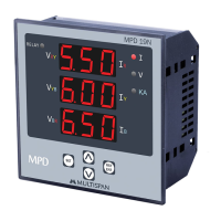
Identifies the specific model of the digital panel meter.
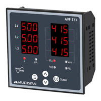
Details the display type and size of the meter.
Specifies the physical dimensions of the meter unit.
Indicates the required dimensions for panel mounting.
Defines the voltage input ranges and categories.
Specifies the current input ranges and selectable ratios.
Details the power requirements for the instrument.
Indicates the supported power systems (e.g., 3Ph-4W).
Specifies the front-side protection rating as per standards.
Defines the acceptable ambient temperature range for operation.
Specifies the maximum non-condensing humidity for operation.
Configures the delay time after the unit is powered on.
Sets the initial time delay parameter for operation.
Sets the under-current threshold based on CT ratio selection.
Defines the time duration for under-current detection.
Sets the over-current threshold based on CT ratio selection.
Configures the time and curve for overload detection.
Specifies the characteristics of the overload trip curve.
Sets the over-voltage threshold (50-500V P-P).
Defines the time duration for over-voltage detection.
Sets the under-voltage threshold (50-500V P-P).
Defines the time duration for under-voltage detection.
Configures fault indication for relay ON/OFF status.
Enables or disables the single-phase preventer function.
Sets the time limit for single-phase detection.
Configures the threshold for short-circuit detection.
Adjusts the scaling for certain parameters.
Sets the parameter for the lock rotter point.
Configures settings related to phase unbalance.
Sets the percentage threshold for unbalance detection.
Defines the time duration for unbalance detection.
Details the over-current tripping function.
Details the under-current tripping function.
Details the over-voltage tripping function.
Details the under-voltage tripping function.
Details the short-circuit tripping function.
Details the single-phase preventer tripping function.
Details the unbalance tripping function.
Details the lock rotter point tripping function.
Configures the automatic reset mode for the instrument.
Configures the manual reset mode for the instrument.
Selects whether to sense voltage or current.
Provides critical safety warnings for operation and wiring.
Offers instructions for safe and proper installation.
Details the physical mounting and panel cutout requirements.
Provides guidance on cleaning and upkeep of the instrument.
| Brand | MULTISPAN |
|---|---|
| Model | MPD-19N |
| Category | Measuring Instruments |
| Language | English |