The Multispan MFM 14DC is a DC Multifunction Meter designed for precise measurement and monitoring of various DC electrical parameters. It offers a comprehensive set of features for both technical specification and user interaction, making it suitable for a wide range of applications requiring accurate DC power monitoring.
Function Description
The MFM 14DC serves as a versatile DC power meter, capable of measuring and displaying DC voltage, DC current, DC power (Watt), and accumulated energy (KWH). It incorporates two relay outputs for control and alarm functions, specifically for over-voltage and under-voltage tripping. The device allows for user-defined set points and trip delays for these relays, offering flexibility in protection and control schemes. A shunt selectable feature enables current measurement through an external shunt, accommodating a broad range of current inputs. The meter also includes a KWH reset function, allowing users to clear accumulated energy readings when needed.
Important Technical Specifications
- Relay Output: The device features two relay outputs, each with a 1C/O (NO-C-NC) type contact. These relays are rated for 10A at 230V AC or 28V DC (resistive load), providing robust switching capabilities for various control applications.
- Accuracy: The MFM 14DC boasts a Class 1.0 accuracy, ensuring reliable and precise measurements.
- Input Voltage: It can directly measure DC voltages from 0 to 1000V DC. The accuracy for voltage measurements varies across different ranges: 1% of 19.99V for 0.00-19.99V DC, 1% of 49.99V for 20.0-49.99V DC, 1% of 199.9V for 50.0-199.9V DC, and 1% of 1000V for 200.0-1000V DC.
- Input Current: Current measurement is achieved through an external shunt (0-75mV DC). The shunt selectable range is from 0 to 9999 Amp. The accuracy for DC current is 1% of Full Scale Deflection (FSD).
- Watt Measurement: The device measures power (Watt) from 0000 to 9999 KW, with an accuracy of 1% of FSD.
- KWH Measurement: It accumulates energy (KWH) from 0 to 999999 KWH.
- Auxiliary Power Supply: The meter operates on a wide range auxiliary power supply from 24 to 270V AC/DC, making it adaptable to various power systems. The burden is approximately 4VA at 230V AC.
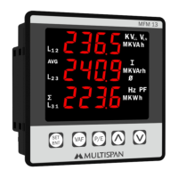
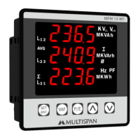
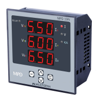
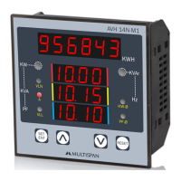
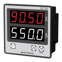
- Display: The MFM 14DC features a 6-digit, 6-line, 7-segment 0.40" RED LED display for KWH, and a 4-digit, 4-line, 7-segment 0.40" RED LED display for other parameters (V, A, W).
- Environmental Conditions: It is designed to operate within a working temperature range of 0 to 55°C and can be stored within the same temperature range. The relative humidity should not exceed 95% RH (non-condensing).
- Protection Level: The front side of the device offers IP-65 protection as per IS/IEC 60529:2001, ensuring resistance against dust and water ingress.
- Dimensions: The meter has a compact size of 96 (H) x 96 (W) x 54 (D) mm, with a panel cutout dimension of 92 (H) x 92 (W) mm.
Usage Features
- Parameter Setting: The device allows users to enter a parameter setting mode by pressing the "PRG" key for 5 seconds. In this mode, users can configure various settings.
- Relay Set Points: Users can set two independent set points (Set Point 1 for Relay 1 and Set Point 2 for Relay 2) for voltage, with a range of 0 to 1000V.
- Trip Delay: Adjustable trip delays (Delay 1 for Relay 1 and Delay 2 for Relay 2) can be configured from 0 to 100 seconds, allowing for transient suppression and preventing nuisance tripping.
- Shunt Selection: The shunt selectable range (0 to 9999 Amp) can be set to match the external shunt used for current measurement.
- KWH Reset: A dedicated "RESET" key allows for resetting the accumulated KWH reading. This function requires a long press of the "RESET" key.
- Fault Reset: The "RESET" key also serves to clear any faults.
- Navigation: "PRG" key is used to set parameter values and save/exit settings. "INC" and "DEC" keys (represented by up and down arrows) are used to increment and decrement parameter values respectively.
- Display Indication: The display clearly shows KWH value, DC Volt, DC Amp, and DC Watt. It also indicates the status of Relay 1 (R1) and Relay 2 (R2) and provides a "Relay For Over Voltage & Under Voltage Tripping" indication.
Maintenance Features
- Cleaning: The equipment should be cleaned regularly to prevent blockage of ventilating parts. A clean, soft cloth should be used for cleaning; isopropyl alcohol or other cleaning agents are not recommended.
- No User-Replaceable Fuses: The fusible resistor within the device is not user-replaceable, emphasizing the need for professional servicing if internal components require attention.
Safety Precautions and Installation Guidelines
The manual stresses the importance of reading and following all safety warnings and instructions to prevent fire, electrical shock, or other issues. It highlights that failure to operate the instrument correctly or handle it as specified by the manufacturer may impair the provided protection.
- Electrical Safety: Power supply to the equipment must be OFF during wiring. Terminals should not be touched when power is supplied.
- Wiring: Use wires with adequate rating and twists for electromagnetic interference reduction. Cable used for power connection must have a cross-section of 1mm² or greater and insulation capacity of at least 1.5kV.
- Installation Environment: The unit should be fitted into a panel cutout with proper dimensions and should not be placed near heating sources, caustic vapors, oil steam, or other unwanted process byproducts.
- Terminal Connections: Use specified crimp terminals (M3.5 screws) and tighten them with a torque of 1.2 N.m. Unused terminals should not be connected.
- Circuit Breaker/Mains Switch: A circuit breaker or mains switch must be installed between the power source and the supply terminal for easy ON/OFF functionality, placed in an easily accessible location.
- Contamination Prevention: Prevent metal pieces, wire clippings, or fine metallic fillings from entering the product during installation to avoid safety hazards.
- Operating Conditions: The instrument must be used and stored within the specified ambient temperature and humidity ranges.