This document describes the MFM-14 DC-M1, a DC Multifunction Meter designed for accurate measurement and monitoring of DC electrical parameters.
Function Description
The MFM-14 DC-M1 is a multifunction meter capable of measuring and displaying various DC electrical parameters. Its primary function is to provide real-time readings of DC Voltage, Current, Watt, and Kilowatt-hour (kWh). The device features a clear digital display that shows these values, making it easy for users to monitor the electrical status of their systems. It also includes a shunt selectable range, allowing it to be adapted for different current measurement requirements. The meter supports MODBUS communication, enabling integration into larger control and monitoring systems. This allows for remote data acquisition and control, making it suitable for industrial and commercial applications where centralized monitoring is essential. The device can be configured to reset kWh values, adjust baud rate, parity, and other communication parameters, providing flexibility in its application.
Important Technical Specifications
Display and Keys:
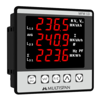
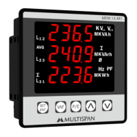
- Display: 6 Digit, 7 seg. 0.40" RED for kWh; 3 Digit, 7 seg. 0.40" RED for V, A, W.
- Keys: RESET, PRG, INC, DEC.
Dimensions:
- Size (mm): 96 (H) x 96 (W) x 54 (D) mm.
- Panel Cutout: 92 (H) x 92 (W) mm.
Auxiliary Power Supply:
- Power Supply: 100V to 270V AC.
- Burden: Approx 5VA @ 230V AC.
Input Specification:
- Input Current: Through external shunt (-75mV to +75mV DC).
- Shunt Selectable: 5 to 9999 Amp.
- Direct voltage DC: 0 to 1000V DC.
Calculated Parameters:
- DC Voltage:
- 0.00 - 49.99 V DC: 1% of 49.99V
- 50.0 - 199.9 V DC: 1% of 199.9V
- 200.0 - 399.9 V DC: 1% of 399.9V
- 400.0 - 1000 V DC: 1% of 1000V
- DC Current: -999 - 9999 A DC.
- Watt: -999 - 9999 KW.
- KWH: 0 - 999999 KWH: 1% of FSD.
Accuracy:
Environmental Condition:
- Working Temperature: 0 to 55°C.
- Storage Temperature: 0 to 55°C.
- Relative Humidity: 95% RH Non-condensing.
- Protection Level: IP-65 (Front side As per IS/IEC 60529: 2001).
Mechanical Installation:
- Panel Cutout Dimension (mm): 92 x 92 mm.
- Dimension (mm): 96 x 96 x 54 mm.
Terminal Connection:
- Modbus: MFM 14DC-M1-A2-00.
- Voltage: 0 to 1000V DC.
- Current: -999 to 9999 Amp; DC.
- Input: -75 to +75mV.
- Auxiliary Supply: 100-270V AC, Class 1.0.
Modbus (MFM-14 DC-M1) Parameters:
- Slave Address: 1 to 127.
- Baudrate: 2400, 4800, 9600, 19200, 38400bps.
- Parity: None, Even, Odd.
- Datatype: Float.
- Frame Delay Time: 0 to 100 milli sec.
- Read Function Register: 0x03 and 0x04.
- Write Function Register: 0x06 and 0x10.
- Register Data Type (Float):
- kWh Value: Register 0, 2.
- DC Voltage: Register 4.
- DC Current: Register 6.
- DC Watt: Register 8.
- Watt/Kilo Watt Status: Register 10 (Selection: Watt=0, Kilo Watt=1).
- Reset KWh: Register 16.
- Address: Register 18.
- Baudrate: Register 20 (Selection: 2400=0, 4800=1, 9600=2, 19200=3, 38400=4).
- Parity: Register 22 (Selection: None=0, Even=1, Odd=2).
- Data Type: Register 24 (Float=1).
- Frame Delay Time: Register 26.
- Shunt Value: Register 28.
Usage Features
Key Operation:
- To enter in parameter setting: Press PRG key for 5 seconds.
- To reset the KWH value: Press RESET key for 5 seconds.
- To set parameter value: Press PRG key.
- To increment parameter value: Press UP arrow key.
- To decrement parameter value: Press DOWN arrow key.
- To set parameter to be save & exit: Press PRG key.
Parameter Setting:
- Password (10): To enter parameter setting, input password '10'.
- Shunt Selectable Range: Set shunt value from 5 to 9999 Amp.
- KWH Reset Password (15): To reset KWH, input password '15' and confirm with 'YES'.
- To change parameter value: Press UP or DOWN arrow keys.
Modbus Setting:
- Password (35): To enter Modbus setting, input password '35'.
- Slave Address: Set slave address from 1 to 127.
- Baudrate: Select baudrate from 2400, 4800, 9600, 19200, 38400 bps.
- Parity: Select parity as None, Even, or Odd.
- Data Type: Set data type to Float.
- Frame Delay Time: Set frame delay time from 0 to 100 ms.
Safety Precaution:
- Read the "Safety Warnings" in the instruction manual carefully.
- Follow the safety rules to prevent fire, trouble, electrical shock, etc.
- Ensure proper wiring and measurement.
- If the equipment is not handled in a manner specified by the manufacturer, it might impair the protection provided by the equipment.
- Read complete instructions prior to installation and operation of the unit.
- WARNING: Risk of electric shock.
Warning Guidelines:
- Risk of electric shock:
- The device must be kept OFF while doing the wiring arrangement.
- Avoid touching the terminals while power is being supplied.
- Reduce electromagnetic interference by using twisted wire or wires of the same equal size.
- Use cable with shortest connection.
- Use cross section of 1mm² or greater for wires.
- Wires should have insulation capacity more than 1.5KV.
- A better anti-noise effect can be expected by using standard power supply cable for the instrument.
Installation Guidelines:
- Do not allow pieces of metal, wire clippings, or fine metallic fillings from installation to enter the product.
- Prepare the panel cutout with proper dimensions.
- Fit the unit into the panel with the help of clamp given.
- The equipment in its installed state must not come in close proximity to any heating source, caustic vapors, oil steam, or other unwanted process byproducts.
- Use the specified size of clamp terminal (M3.5 screws) to wire the terminal block. Tighten the screws on the terminal block using the tightening torque of the range of 1.2 N-m.
- Do not connect anything to unused terminals.
- Ensure all metal, wire clippings, or fine metallic fillings are prevented from entering the product.
- Circuit breaker or mains switch must be installed between power source and supply terminal to facilitate power ON or OFF function.
- The device must be installed at a convenient place normally accessible to the operator.
- Use and store the instrument within the specified ambient temperature and humidity ranges.
Maintenance Features
- The equipment should be cleaned regularly to avoid blockage of ventilating parts.
- Clean the equipment with a clean soft cloth. Do not use isopropyl alcohol or any other cleaning agent.
- Fusible resistor must not be replaced by operator.