Do you have a question about the MULTISPAN AVH 14N-M1 and is the answer not in the manual?
Details electrical input specifications like voltage, current, frequency, and CT ratios.
Describes the device's display capabilities and user interface keys.
Provides physical dimensions and panel cutout sizes for installation.
Specifies the required auxiliary power supply voltage and consumption.
Outlines operating conditions like protection level, temperature, and humidity.
Lists parameters shown on the device display and their corresponding measurement ranges.
Guide to entering the Modbus menu and configuring parameters like address, baud rate, and parity.
Details Modbus parameter configuration options including address, baud rate, and parity.
Steps to select and configure the Current Transformer (CT) ratio for accurate readings.
Procedures for enabling/disabling load hour and RPM functionalities.
Lists Modbus registers for reading and writing various electrical parameters and settings.
Specifies Modbus communication settings: device address, baud rate, parity, and data types.
Important notes on meter usage, external CT selection, and accuracy considerations.
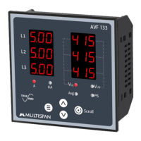
Displays voltage (V) and frequency (Hz) readings for 3-phase systems.
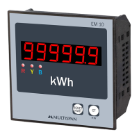
Shows power (KW) and energy (KWH) values for 3-phase systems.
Displays apparent power (KVA) and reactive power (KVAr) for 3-phase systems.
Shows energy (KWH) and reactive power (KVAr) readings for 3-phase systems.
Displays phase voltages (VLN) and phase currents (I) for 3-phase systems.
Shows phase power factor (PF) for each phase in 3-phase systems.
Displays load hours (Lhrs) and related time parameters.
Shows RPM and load hour readings for operational monitoring.
Displays no load hour readings and related time parameters.
Shows KVAh (apparent energy) readings for 3-phase systems.
Displays KVArh (reactive energy) readings for 3-phase systems.
Provides detailed dimensions and panel cutout requirements for unit installation.
Instructions for fitting the unit into the panel, avoiding heat sources, and using terminals.
Critical warnings about the risk of electric shock and the need to follow safety instructions.
Guidelines for safe operation, including power supply checks and reading instructions.
Precautions to prevent electric shock, including keeping power OFF during wiring.
Tips for reducing electromagnetic interference using adequate wiring.
Guidelines for installing the unit, avoiding debris, and using accessible circuit breakers.
Instructions for cleaning the equipment and caution against replacing fusible resistors.
The Multispan AVH 14N-M1 is a versatile and robust user manual designed for comprehensive power measurement and monitoring in industrial and commercial settings. This device is engineered to provide accurate readings of various electrical parameters, making it an essential tool for energy management, system diagnostics, and operational efficiency. Its user-friendly interface and detailed documentation ensure ease of installation, configuration, and daily operation.
The primary function of the Multispan AVH 14N-M1 is to measure and display a wide range of electrical parameters, including voltage, current, power, energy, and frequency. It supports both 3-phase 3-wire and 3-phase 4-wire systems, offering flexibility for diverse applications. The device is capable of measuring direct voltage AC, with a range of 30 to 300V (L-N) and 50 to 500V (L-L), and current AC from 50mA to 5A directly, or up to 6000A with a selectable primary CT ratio. This broad measurement capability allows for detailed analysis of power consumption and quality.
One of the key features is its ability to calculate and display active power (KW), apparent power (KVA), and reactive power (KVAr), both total and per phase. It also tracks active energy (KWH), apparent energy (KVAh), and reactive energy (KVArh), providing cumulative data for long-term energy auditing. The device measures power factor (PF) average and per phase, which is crucial for understanding system efficiency and identifying potential issues.
The Multispan AVH 14N-M1 also incorporates a maximum demand function, which records the highest average power value over a defined time interval (MD Time). This feature is invaluable for managing peak loads and optimizing energy tariffs. The MD time is selectable, with a default of 15 minutes, allowing users to tailor the measurement period to their specific needs.
For communication and integration into larger systems, the device supports MODBUS. Users can configure MODBUS parameters such as address, baud rate, parity, and data type, enabling seamless data exchange with supervisory control and data acquisition (SCADA) systems or other monitoring platforms. The MODBUS functionality allows for remote access to all measured parameters, facilitating centralized monitoring and control.
The device also includes features like load hours and no-load hours, which help in understanding equipment utilization and operational patterns. It can measure RPM, which is useful in applications involving rotating machinery. The ability to enable or disable load hour and RPM functions adds to its adaptability.
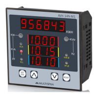
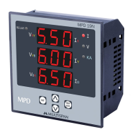
The Multispan AVH 14N-M1 is designed for intuitive operation, featuring a clear display and straightforward navigation. The display consists of an upper 6-digit, 7-segment 0.40" RED LED for KWH and a lower 4-digit, 7-segment 0.40" RED, 3-line display for other parameters. This dual display ensures that critical information is always visible.
Configuration of the device is made simple through a set of keys: SET/ENT, INC, DEC, and RESET. These keys allow users to access and modify various settings, including CT ratio, connection type (3-phase 3-wire or 3-phase 4-wire), and MODBUS parameters. The connection type can be changed by pressing the RESET key and powering on the instrument, with the setting saved by powering off.
The device provides a comprehensive parameter display, allowing users to view real-time measurements and accumulated data. Parameters such as line voltage (Vpp), phase-neutral voltage (Vpn), line current (~A), active power (KW), active energy (KWH), apparent energy (KVAh), reactive energy (KVArh), power factor (PF), apparent power (KVA), and frequency (Freq) are all accessible. Additionally, load hours, no-load hours, RPM, and maximum demand values (MD KW, MD KVA, MD KVAr) can be monitored.
Resetting accumulated values like KWH, KVAh, and KVArh, as well as maximum demand (MD), is a guided process using password protection to prevent accidental changes. This ensures data integrity while allowing authorized personnel to clear readings when necessary. The CT selection procedure is also user-friendly, enabling the configuration of primary CT ratios from 5 to 6000 Amp, which is crucial for accurate current measurements.
The physical design of the device, with dimensions of 96 (H) x 96 (W) x 52 (D) mm and a panel cutout of 92 (H) x 92 (W) mm, makes it suitable for standard panel mounting. The terminal diagram is clearly labeled, simplifying the wiring process. Safety precautions are emphasized, including instructions for proper installation, wiring, and power supply connections to prevent electric shock and ensure reliable operation.
The Multispan AVH 14N-M1 is built for durability and minimal maintenance, but adherence to recommended guidelines ensures its longevity and accurate performance. The device has an IP-65 protection level on the front side, making it resistant to dust and water splashes, which is beneficial in various industrial environments.
Regular cleaning is recommended to prevent blockage of ventilating parts. The manual specifies cleaning the equipment with a clean soft cloth and advises against using isopropyl alcohol or any other cleaning agents that could damage the device. This simple routine helps maintain optimal operating conditions and prevents overheating.
The device is designed to operate within an ambient temperature range of 0°C to 55°C and a relative humidity of up to 95% RH (non-condensing). Storing and using the instrument within these specified environmental conditions is crucial for its reliable operation and to prevent damage.
The manual also provides important notes regarding the use of external CTs. It suggests selecting external CTs such that the actual load does not fall below 40% of the CT's ampere rating. This recommendation helps achieve more accurate cumulative energy values over time, highlighting the importance of proper system integration for optimal performance. For instance, with a 100/5 A CT, accuracy is best when the load is above 40 Amperes.
The device's construction is robust, and the manual provides instructions for proper installation, including preparing the panel cutout, fitting the unit with clamps, and tightening terminal block screws to a specified torque (1.2 N.m). These steps ensure a secure and stable installation, reducing the likelihood of operational issues due to loose connections or improper mounting.
The manual explicitly states that the fusible resistor must not be replaced by the operator, indicating that internal repairs should be handled by qualified personnel. This emphasizes the importance of professional servicing for complex issues, ensuring the device's safety and continued functionality.
Overall, the Multispan AVH 14N-M1 is a reliable, feature-rich power measurement device designed for ease of use and long-term performance, with clear guidelines for both operation and maintenance.
| Model | AVH 14N-M1 |
|---|---|
| Category | Measuring Instruments |
| Mounting | Panel Mount |
| Display | Digital LED |
| Measurement Range | 0 to 600V AC |
| Accuracy | ±0.5% |
| Power Supply | 230V AC, 50/60Hz |
| Weight | 250 g |