This document describes the PI-54 Process Indicator, an operating manual detailing its technical specifications, usage, and maintenance.
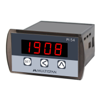
The PI-54 is a 4-digit process indicator featuring a 0.39-inch red LED display. Its primary function is to display process values based on various input signals. The device is designed for panel mounting, with dimensions of 38mm (height) x 68mm (width) x 63mm (depth) and a panel cutout of 31mm x 54.5mm.
Technical Specifications:
- Display: 4 Digit 7 segment, 0.39" red LED Display.
- Size (H x W x D): 38mm x 68mm x 63mm.
- Panel Cutout: 31mm x 54.5mm.
- Input: Supports 0-10V DC, 0-20mA DC, and 4-20mA DC signals.
- Range: Selectable from -999 to 9999.
- Power Supply: 100 to 270V AC, 50/60Hz, approximately 1VA.
- Protection Level: IP-65 (Front side) as per IS/IEC 60529:2001.
- Operating Temperature: 0°C to 55°C.
- Relative Humidity: Up to 95% RH Non-Condensing.
Usage Features:
The PI-54 offers both basic and factory configuration options, allowing users to customize its operation.
Basic Configuration:
To enter user configuration, press the SET and < keys together for 5 seconds.
- Process Value: Displays the current process value (e.g., 1234).
- Parameter Message: Displays "P A A" when entering parameter settings.
- Input Selection: Users can select the input type (0-10V DC, 0-20mA DC, or 4-20mA DC) using the arrow keys.
- 0-10V DC: Displays "0 - 10".
- 0-20mA DC: Displays "0 - 20".
- 4-20mA DC: Displays "4 - 20".
- Decimal Point (d P): Allows setting the position of the decimal point (e.g., "0000").
- Low Range (L r n 6): Configures the minimum display value for the selected input range (e.g., "0000").
- High Range (H r n 6): Configures the maximum display value for the selected input range (e.g., "1000").
- Filter Time (F L t r): Sets the filter time from 0.1 seconds to 10.0 seconds (e.g., "0 0 0.5"). This helps stabilize readings.
- Offset (O F S E): Allows setting an offset value within a range of ±999 counts (e.g., "0000").
- Correction Factor (C F C): Configures a correction factor within a range of ±999 counts (e.g., "0000").
- Signal Low Level (S L L): Specifically for 4-20mA input, this sets the low-level signal value (Ampere range: 0-5mA), typically between 0.0 and 5.0 (e.g., "A 3.5").
To confirm changes and move to the next step, press the SET key. To save and exit the configuration, press the SET key for 3 seconds.
Factory Setting:
To enter factory setting, press the SET and A keys together for 5 seconds. The factory settings provide default values for various parameters:
| Parameter |
0-10V DC |
0-20mA DC |
4-20mA DC |
| Low Range |
0 |
0 |
0 |
| High Range |
1000 |
2000 |
2000 |
| Decimal Point |
0000 |
0000 |
0000 |
| Filter Time |
0.5 sec |
0.5 sec |
0.5 sec |
| Off-set |
0 |
0 |
0 |
| Correction Factor |
0 |
0 |
0 |
| Signal Low Level |
- |
- |
3.5 mA |
To save and exit factory settings, press the SET key for 3 seconds.
Important Notes on Usage:
- Auto-exit occurs after 25 seconds if no activity, and menu exits without saving.
- The configurable range is -999 to 9999.
- Signal low-level mode is exclusively for 4-20mA DC input, with a range of 0.0-5.0 mA DC.
- Reverse scaling of the range is possible in user configuration.
- Upon power-on, the instrument displays a specific pattern: "8.8.8.8" for 3 seconds, followed by "0 - 10" (or default analog input) for 2 seconds, and then the "Process Value".
Connection Diagram:
The device features a 6-terminal block for connections:
- Terminals 1 & 2: Power supply (100 to 270V AC, 50/60Hz, 1VA). Terminal 1 is Neutral (N), Terminal 2 is Live (L).
- Terminals 3 & 4: Input (I/P) for 0-20mA DC or 4-20mA DC. Terminal 3 is negative (-), Terminal 4 is positive (+).
- Terminals 5 & 6: Input (I/P) for 0-10V DC. Terminal 5 is negative (-), Terminal 6 is positive (+).
Safety Precautions:
- Always follow safety codifications, symbols, and instructions.
- Improper handling may impair protection.
- Read instructions before installation and operation.
- WARNING: Risk of electric shock.
Warning Guidelines:
- Turn OFF power supply during wiring.
- Use adequate wiring with shortest connections to reduce electromagnetic interference.
- Cable for power source must have a cross-section of 1mm² or greater and insulation capacity of at least 1.5kV.
- Use standard power supply cable for better anti-noise effect.
Installation Guidelines:
- The equipment is built-in type and becomes part of the main control panel. Terminals should not be accessible to the end user after installation.
- Prevent metal pieces, wire clippings, or fine metallic fillings from entering the product to avoid safety hazards or electrical shock.
- Install a circuit breaker or mains switch between the power source and supply terminal for ON/OFF function, accessible to the operator.
- Operate and store the instrument within specified ambient temperature and humidity ranges.
Mechanical Installation:
- Prepare a panel cutout with dimensions: 31mm (height) x 54.5mm (width).
- Fit the unit into the panel using the provided clamp.
- Ensure the equipment is not near heating sources, caustic vapors, oils, steam, or other unwanted process by-products.
- Use M3.5 screws for wiring the terminal block, tightening to a torque of 1.2 N.m.
- Do not connect anything to unused terminals.
Maintenance Features:
- Regularly clean the equipment to prevent blockage of ventilating parts.
- Use a clean soft cloth for cleaning. Do not use isopropyl alcohol or other cleaning agents.
- The fusible resistor must not be replaced by the operator.
For updated operating information and support, contact Multispan India via helpline (+91-9978991474/76/82) or email (service@multispanindia.com).