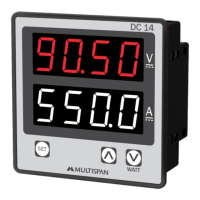
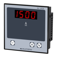
The AMULTISPAN DC Multifunction Meter, model DC-14, is a versatile instrument designed for measuring and displaying various DC electrical parameters. It features a compact design suitable for panel mounting and provides clear digital readouts for easy monitoring.
Function Description:
The DC-14 meter is capable of measuring DC voltage, DC current, and calculating DC power (Watt). It operates by taking input from an external shunt for current measurement and direct voltage input for voltage measurement. The device displays these parameters on a dual-line, 4-digit, 7-segment display, with the top line in red (0.8" height) and the bottom line in white (0.8" height). Users can navigate between Amp & Voltage and Watt display pages using a dedicated key. The meter also includes parameter setting capabilities, allowing users to configure shunt selectable range and correction factors for both current and voltage measurements. Error codes are displayed to indicate issues such as shunt errors or excessive input signals.
Important Technical Specifications:
Environmental Conditions:
- Working Temperature: 0 to 55°C
- Storage Temperature: 0 to 55°C
- Relative Humidity: 95% RH Non-Condensing
- Protection Level: IP-65 (Front side as per IS/IEC 60529: 2001)
- Input Current: Through external shunt (-75mV to +75mV DC)
- Shunt Selectable Range: -999 to 9999 Amp
- Direct Voltage DC: 0 to 1000V DC
Calculated Parameters & Accuracy:
- DC Voltage:
- 0.00 - 49.99 V DC: 1% of 49.99V
- 50.0 - 199.9 V DC: 1% of 199.9V
- 200.0 - 399.9 V DC: 1% of 399.9V
- 400.0 - 1000 V DC: 1% of 1000 V
- DC Current: -999 - 9999 A DC
- WATT: 0000 - 9999 KW: 1% of FSD
- Accuracy Class: 1.0 (Standard)
Display & Keys:
- Display: 4 Digit, 1 Line 7 seg. 0.8" RED (top line); 4 Digit, 1 Line 7 seg. 0.8" White (bottom line)
- Key Functions: Set, INC (Increment), DEC (Decrement)
Dimensions:
- Size (mm): 96 (H) x 96 (W) x 54 (D) mm
- Panel Cutout (mm): 92 (H) x 92 (W) mm
Auxiliary Power Supply:
- Power Supply: 100V to 270V AC, 50/60Hz
- Burden: Approx 3VA @ 230V AC
Usage Features:
Parameter Setting:
The device allows users to enter a parameter setting mode by pressing the SET key for 5 seconds. A password (default 10) is required to access these settings.
- Shunt Selectable Range (5Hnt): Configurable from -999 to 9999 Amp, with a default value of 100.
- Correction Factor (C.F): Available for both current and voltage measurements, adjustable from 0±99.9.
Parameters are saved by pressing the SET key again.
Terminal Connection:
The meter provides clear terminal connections for its auxiliary power supply (L, N), direct voltage input (+V DC, GND), and current shunt input (+I DC, GND). It supports a voltage input range of 0 to 1000V DC and a current input range of -999 to 9999 Amp DC via a -75mV to +75mV shunt.
Display Indication:
- Amp & Voltage Page: Displays current (e.g., 195.5 A) and voltage (e.g., 150.0 V).
- Watt Page: Displays power (e.g., 999 W). If the watt value exceeds 999, it is displayed in Kilowatts (KW), for example, 1.001 KW.
- Error Display:
- "Shunt error or shunt connection is open" is indicated by "SHEr".
- "Shunt input signal is excess more than 75mV DC" is indicated by "OUer".
Mechanical Installation:
- Prepare a panel cutout with dimensions 92mm (H) x 92mm (W).
- Fit the unit into the panel using the provided clamp.
- Ensure the equipment is not installed near heating sources, caustic vapors, oil steam, or other unwanted process byproducts.
- Use specified size crimp terminals (M3.5 screws) for wiring, tightening screws to a torque of 1.2 N.m.
- Do not connect anything to unused terminals.
Safety Precautions:
- Read the instruction manual thoroughly for correct use.
- Failure to follow safety rules can cause fire, trouble, or electrical shock.
- Operate the instrument on the correct power supply and voltage rating.
- If not handled as specified, protection may be impaired.
- Risk of electric shock: Power supply must be OFF during wiring. Do not touch terminals when power is supplied.
- Use adequately rated and twisted wires for connections to reduce electromagnetic interference.
- Cable for power source connection must have a cross-section of 1mm or greater with insulation capacity of at least 1.5kV.
- Use standard power supply cable for better anti-noise effect.
- Install a circuit breaker or mains switch between the power source and supply terminal for easy power ON/OFF, placed in an accessible location.
- Use and store the instrument within specified ambient temperature and humidity ranges.
Maintenance Features:
- Regular Cleaning: The equipment should be cleaned regularly to prevent blockage of ventilating parts.
- Cleaning Agent: Clean the equipment with a clean soft cloth. Do not use isopropyl alcohol or any other cleaning agent.
- Fuse Replacement: Fusible resistors must not be replaced by the operator.