Do you have a question about the MULTISPAN AVF-133 and is the answer not in the manual?
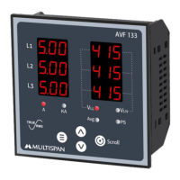
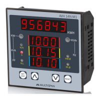
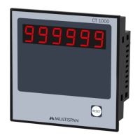
Details the 3-digit, 6-line, 7-segment red LED display.
Explains the functions of the keys: Menu, Inc, Dec, Scroll.
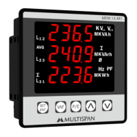
Lists LED indications: A, KA, VLL, VLN, Avg, PS.
Specifies the operating temperature range from 0 to 55°C.
Specifies the storage temperature range from 0 to 55°C.
States the non-condensing humidity limit as 95% RH.
Details IP-65 rating for the front side as per IS/IEC 60529.
Provides overall device dimensions: 96(H) x 96(W) x 55(D) mm.
Specifies the required panel cutout size: 92(H) x 92(W) mm.
Highlights separate Amp display, wiring systems, and load hour/RPM indication.
Details AC voltage and burden specifications.
Lists primary/secondary CT ratio, burden, overload, and frequency.
Lists parameters like Voltage, Current, Frequency, Phase Sequence, Load Hour.
States the standard accuracy class as 0.5.
Specifies power supply voltage and burden.
Instructions to enter parameter setting mode.
Instructions to change pages in operator mode.
Instructions to increment/decrement values in parameter setting.
Instructions to set parameters and exit.
Instructions for scroll and hold function.
Explains PS LED indication for incorrect phase sequence.
Describes KA LED indication when current exceeds 999 Amp.
Indicates DP blinking on load hour page when incrementing.
Setting CT ratio and network connection.
Procedure to reset load hour.
Setting percentage for display.
Enabling/disabling RPM display.
Setting pole for display.
Example display for Average, Load Hour & RPM in 10-2W.
Displaying VLN voltage values for 30-4W system.
Displaying VLL voltage values for 30-4W system.
Displaying frequency values for 30-4W system.
Displaying average voltage and current for 30-4W system.
Displaying load hour for 30-4W system.
Displaying RPM values for 30-4W system.
Displaying VLL voltage values for 30-3W system.
Displaying average voltage and current for 30-3W system.
Displaying load hour for 30-3W system.
Displaying RPM values for 30-3W system.
Guidance for integrating the unit into a main control panel.
Warning against placing near heating sources or caustic vapors.
Requirement for a circuit breaker for power ON/OFF.
Advice on using within specified ambient temperature and humidity.
Instructions for preparing panel cutout and fitting the unit.
Guidance on avoiding proximity to heating sources or vapors.
Specifies torque for wiring terminal blocks (1.2 N.m).
Instruction not to connect anything to unused terminals.
Wiring diagram for 3 Phase - 4Wire system.
Wiring diagram for 3 Phase - 3Wire system.
Wiring diagram for 1 Phase - 2Wire system.
Instructions to keep power OFF during wiring.
Using adequate rated wires with twists for EMI reduction.
Recommends cable cross-section (1mm) and insulation capacity (1.5kV).
Follow safety codifications, symbols, and instructions.
Handle equipment as specified to maintain protection.
Complete reading of instructions before installation and operation.
Clean regularly to avoid blockage of ventilating parts.
Use a clean soft cloth; avoid isopropyl alcohol.
Fusible resistor must not be replaced by the operator.
The Multipsan AVF-133 is a 3-Phase VAF (Voltage, Amperage, Frequency) Meter designed for industrial and commercial applications to monitor electrical parameters.
The AVF-133 provides real-time measurement and display of voltage (line-to-neutral and line-to-line), current (per phase and average), and frequency. It also indicates phase sequence, load hours, and RPM. The device supports various wiring systems including 3-phase 4-wire, 3-phase 3-wire, and 1-phase 2-wire configurations. It features a clear 3-digit, 6-line, 7-segment 0.36" red LED display for easy readability. Key operations allow users to navigate menus, increment/decrement values, and save settings. LED indicators provide visual cues for various parameters like A, kA, VLL, VLN, Avg, and PS (Phase Sequence).
Display, Key & LED:
Environmental Conditions:
Dimension:
Input:
Calculated Parameters:
Accuracy:
Auxiliary Power Supply:
Features:
Key Operation:
Parameter Setting:
Installation Guidelines:
Wiring Guidelines:
Maintenance:
Safety Precaution:
| Brand | MULTISPAN |
|---|---|
| Model | AVF-133 |
| Category | Measuring Instruments |
| Language | English |