Do you have a question about the MULTISPAN MFM-13 and is the answer not in the manual?
Details input signal types, CT/PT primary/secondary settings, frequency, load hours, and RPM specifications.
Specifies the measurement ranges for total and per-phase kW, kVA, kVAr, kWh, kVAh, and kVArh.
Specifies the auxiliary supply voltage requirements, power consumption, and the device's accuracy class.
Details the operating temperature, relative humidity limits, and protection level (IP rating) of the meter.
Provides the overall dimensions of the meter and the required panel cutout size for installation.
Illustrates the terminal layout for connections and provides model-specific electrical ratings and accuracy class.
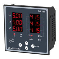
Explains how to navigate and view different pages (VAF, Power & Energy) using the device keys.
Details the process for entering parameter setting mode and adjusting values using increment/decrement keys.
Covers configuration for Load Hour, Load Hour Percentage, RPM, Pole, and Pulse settings.
Provides instructions for panel cutout, unit fitting, placement, and terminal connection using specified crimp terminals.
Advises on internal wiring, preventing debris, installing circuit breakers, and operating within specified ranges.
Outlines regular cleaning practices and cautions against operator replacement of fusible resistors.
Emphasizes adherence to safety instructions and warns about electric shock risks and proper wiring.
Details voltage, current, frequency, and power factor measurements across different phases.
Presents measurements for kW, kVA, kWh, and kVArh per phase and total for 3-phase systems.
Shows V, A, Hz, PF, kWh, kVAh, and kVArh for single-phase 2-wire configurations.
Provides detailed voltage (L-N, L-L), current, frequency, and power factor readings.
Displays individual phase power factors and the overall system power factor.
Lists per-phase and total kW, kVA, kWh, kVAh, and kVArh for 3-phase systems.
Displays total load hours, no-load hours, and the rotational speed (RPM).
Shows total kVA, kvar, kW, kWh, kVAh, and kvarh for single-phase 2-wire configurations.
Allows resetting all parameters to their default values after password entry.
Enables resetting kWh, kVAh, kVArh, Load Hour, or No Load Hour individually.
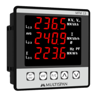
The MULTISPAN MFM-13 is a Multi Function Meter designed for comprehensive electrical parameter measurement and monitoring. It is suitable for various industrial and commercial applications, offering a wide range of technical specifications and user-friendly features.
The MFM-13 measures and displays a broad spectrum of electrical parameters, including voltage (L-N, L-L, average), current (per phase, average), system frequency, power (kW total, kW per phase, kVA total, kVA per phase, kVAr total, kVAr per phase), and energy (kWH total, kVAh total, kVArh total). It also tracks load hours, no-load hours, and RPM. The device supports 3-phase 3-wire, 3-phase 4-wire, and 1-phase 2-wire systems, making it versatile for different electrical configurations.
| Brand | MULTISPAN |
|---|---|
| Model | MFM-13 |
| Category | Measuring Instruments |
| Language | English |