EasyManua.ls Logo

MULTISPAN PI 38 User Manual

MULTISPAN PI 38
3 pages
To Next Page IconTo Next Page
Page #1 background imageLoading...
Page #1 background image
PI 38
INPUT SPECIFICATION:
FEATURES:
Input Types
Elegant appearance and compact in size
Accurate and sturdy in operation
Very easy to operate
I/P Filter Time
Indication
Accuracy
Resolution
Range
Voltage:
Current:
PROCESS INDICATOR
0 to 10V DC
±1% FSD ± 1 digit
(FSD - Full Scale Deflection)
0 to 20mA DC,
4 to 20mA DC
0.1 Sec to 10.0 Sec
Decimal point selectable:
-999 to 9999 (For all I/P)
0.1, 0.01, 0.001, 0001
DISPLAY AND KEY:
DIMENSION:
Display
Size
Keys
Panel Cutout
4 digit, 7 segment, 0.8” RED LED
48 (H) x 96 (W) x 26 (D) mm
SET, SHIFT, INC
45 (H) x 92(W) mm
POWER SUPPLY:
Power
Consuption
(VA Rating)
Supply
Voltage
100 to 270V AC, 50-60Hz
2VA @ 230V AC MAX
TECHNICAL SPECIFICATION
ENVIRONMENT CONDITION:
Relative Humidity
Protection Level
(As per request)
Operating Temp.
0°C to 55°C
UP to 95% RH
(non-condensing)
IP-65 (Front side) As per IS/IEC
60529 : 2001
TERMINAL CONNECTION
4
3
(4-20mA DC or
0-20mA DC)
+
+
Connection for voltage I/P
Connection for current I/P
5
4
(0-10V DC)
48
92
Outline Dimension (mm)
Panel Cutout
Dimension (mm)
96
45
26
4
SET
PI 38
913.8
L
N
3 4 51 2
0/4-20
mA DC
+
+
-
0-10V
DC
MECHANICAL INSTALLATION
Page -1
Question and Answer IconNeed help?

Do you have a question about the MULTISPAN PI 38 and is the answer not in the manual?

MULTISPAN PI 38 Specifications

General IconGeneral
BrandMULTISPAN
ModelPI 38
CategoryMeasuring Instruments
LanguageEnglish

Summary

Technical Specifications

Features

Highlights the device's elegant, compact, accurate, sturdy, and user-friendly design.

Input Specifications

Details voltage/current input types, filter time, resolution, range, and accuracy.

Display and Key Information

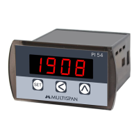
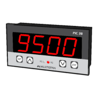
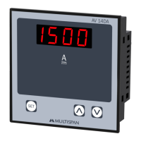
Describes the 4-digit, 7-segment RED LED display and available keys.

Dimension Details

Provides unit size (48x96x26 mm) and panel cutout (45x92 mm) dimensions.

Power Supply Requirements

Specifies supply voltage (100-270V AC) and power consumption (2VA max).

Environmental Conditions

Operating Temperature Range

Specifies the safe operating temperature from 0°C to 55°C.

Relative Humidity Limit

Defines the acceptable non-condensing humidity level up to 95% RH.

Protection Level Standard

Indicates IP-65 protection for the front side as per IS/IEC 60529:2001.

Mechanical Installation Guidelines

Outline Dimensions

Presents the external dimensions of the device in mm.

Panel Cutout Dimensions

Provides the required panel opening dimensions for mounting.

Terminal Connections

Voltage Input (0-10V DC) Wiring

Diagram illustrating the connection for voltage input signals.

Current Input (4-20mA DC) Wiring

Diagram illustrating the connection for current input signals.

Key Operation and Modes

Operator Mode Navigation

Instructions for entering parameter and factory setting modes.

Parameter Setting Mode

Guide to editing, modifying, and saving parameter values.

Maintenance and Safety

Equipment Maintenance

Recommendations for regular cleaning and component handling.

Safety Precautions

Emphasizes strict adherence to safety instructions for personnel and instrument.

Installation Safety Guidelines

Covers general installation practices, foreign object prevention, and power control.

Wiring Warning Guidelines

Highlights risks of electric shock and provides EMI reduction/cable guidelines.

Mechanical Installation Best Practices

Panel Preparation and Fitting

Guides on preparing panel cutouts and fitting the unit securely.

Proximity and Terminal Wiring

Advises on placement relative to heat sources and terminal connection.

Error Display Meanings

Over Range Input

Explains 'QUEr' error for input exceeding specified voltage or current limits.

Low Signal Input

Explains 'LOO' error for current input below the selected low signal level.

Parameter Setting Procedures

Navigating Parameter Settings

Step-by-step guide for setting process value, input type, and decimal point.

Setting Range and Offset

Instructions for configuring low/high range, filter time, and offset values.

Correction Factor and Low Level

Guide to setting correction factor and signal low level for specific inputs.

Factory Setting Configuration

Entering Factory Setting Mode

Procedure to access factory settings using SET + A keys.

Factory Parameter Table

Lists default factory settings for various parameters across input types.

Parameter Range Reference

Parameter Range Definitions

Details the valid range for each configurable parameter.

Related product manuals