This document describes the MFM-142 DC-M1, a DC Multifunction Meter designed for accurate measurement and monitoring of various electrical parameters in DC systems.
Function Description
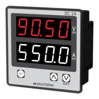
The MFM-142 DC-M1 is a versatile DC multifunction meter capable of measuring and displaying DC Voltage, DC Current, and DC Wattage. It features two relay outputs for control applications and a shunt selectable range for current measurement, making it adaptable to various system requirements. The device also includes an energy accumulation function (kWh) and provides Modbus RTU communication for integration into larger monitoring and control systems.
Important Technical Specifications
Output Specification:
- Relay Output: 2 Nos (Normally Open/Normally Closed - NO/NC)
- Relay Type: 1C/O (NO-C-NC)
- Rating: 10A, 230V AC / 28V DC (Resistive Load)
Communication:
- RS-485 Modbus: The device supports Modbus RTU protocol for remote data acquisition and control.
Accuracy:
- Class 1.0 (Standard): Indicates a measurement accuracy of 1% of the full scale.
Environmental Condition:
- Working Temperature: 0 to 55°C
- Storage Temperature: 0 to 55°C
- Relative Humidity: 95% RH Non-Condensing
- Protection Level (As per Request): IP-65 (Front side as per IS/IEC 60529: 2001)
Technical Specification:
- Input Current: Through external shunt (75mV) (I/P+75mV DC)
- Shunt Selectable: 0 to 9999 Amp
- Voltage: 0 to 1000V DC
- Direct Voltage DC: 0 to 1000V DC
Calculated Parameters:
- DC Voltage:
- 0.00 - 49.99 V DC: 1% of 19.99V
- 50.0 - 199.9 V DC: 1% of 199.9V
- 200.0 - 399.9 V DC: 1% of 399.9V
- 400.0 - 1000 V DC: 1% of 1000V
- DC Current: -999 - 9999 A DC
- Watt: -999 - 9999 KW: 1% of FSD
- KWH: 0 - 999999 KWH
Display & Keys:
- Display: 6 Digit, 7 seg. 0.40" RED
- 4 Digit, 3 Line 7 seg. 0.40" RED
- Key: RESET, PRG, INC, DEC
Dimension:
- Size (mm): 96 (H) x 96 (W) x 54 (D) mm
- Panel Cutout (mm): 92 (H) x 92 (W) mm
Auxiliary Power Supply:
- Power Supply: 100V to 270V AC
- Burden: Approx 5VA @ 230V AC
Usage Features
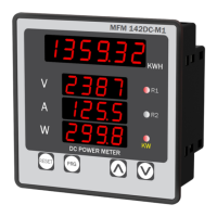
Display Indication:
The device features a clear digital display that shows:
- KWH Value: 1359.32 KWH
- DC Volt: 238.7 V (with R1/R2 indicators for relay status)
- DC Amp: 125.5 A (with R1/R2 indicators for relay status)
- DC Watt: 299.8 W (with R1/R2 indicators for relay status)
- Relay For Over voltage & Under voltage Tripping: Indicates the reason for relay activation.
Key Operation:
The device is operated using three keys: PRG (Program), INC (Increment), and DEC (Decrement).
- To enter in parameter setting: Press PRG key for 5 seconds.
- To reset the KWH value: Press RESET key.
- To set parameter value: Press PRG key.
- To increment parameter value: Press INC key.
- To decrement parameter value: Press DEC key.
- To save & exit: Press PRG key.
Parameter Setting:
The device allows configuration of various parameters:
- Password: (Default: 10)
- Set Point for Relay 2: (Range: 0 to 1000V)
- Shunt Selectable Range: (Range: 0 to 9999Amp)
- Trip Delay for Relay 2: (Range: 0 to 100 sec)
- Set Point for Relay 1: (Range: 0 to 1000V)
- Relay 2 Fault mode: (ON/OFF)
- Trip Delay for Relay 1: (Range: 0 to 100 sec)
- Hysteresis: (Selectable 0 to 100V)
- Relay 1 Fault mode: (ON/OFF)
- KWH Reset: To reset KWH, press PRG key for 5 seconds and enter password (Default: 15). Then select YES/NO for KWH reset.
Modbus (MFM-142 DC-M1) Parameters:
The device supports Modbus RTU communication with configurable parameters:
- Slave Address: 1 to 127
- Baudrate: 2400, 4800, 9600, 19200, 38400bps
- Parity: None, Even, Odd
- Datatype: Float
- Frame Delay Time: 0 to 99 milli sec
- Read Function Register: 0x03 and 0x04
- Write Function Register: 0x06 and 0x10
The Modbus register map includes:
- kWh Value: (Register 1, Data Type Float)
- DC Voltage: (Register 2, Data Type Float)
- DC Current: (Register 3, Data Type Float)
- DC Watt: (Register 4, Data Type Float)
- Watt/Kilo Watt Status: (Register 5, Value 0 for Watt, 1 for Kilo Watt)
- R1 Status: (Register 6)
- R2 Status: (Register 7)
- Reset KWh: (Register 8)
- Address: (Register 9)
- Baudrate: (Register 10)
- Parity: (Register 11)
- Data Type: (Register 12)
- Frame Delay Time: (Register 13)
- Shunt Value: (Register 14)
- SET Point R1: (Register 15)
- Delay 1: (Register 16)
- Relay Fault mode 1: (Register 17)
- Hysterisis 1: (Register 18)
- SET Point R2: (Register 19)
- Delay 2: (Register 20)
- Relay Fault mode 2: (Register 21)
- Hysterisis 2: (Register 22)
Maintenance Features
Mechanical Installation:
- Prepare the panel cutout with proper dimensions as shown above.
- Fit the unit into the panel with the help of clamp given.
- The equipment in its installed state must not come in close proximity to any heating source, caustic vapors, oil steam, or other unwanted process byproducts.
- Use the specified size of crimp terminal (M3.5 screws) to wire the terminal block. Tightening the screws on the terminal block using the tightening torque of the range of 1.2 N.m.
- Do not connect anything to unused terminals.
Installation Guidelines:
- Do not allow pieces of metal, wire clippings, or fine metallic fillings from installation to enter the product or else it may lead to a safety hazard that may in turn endanger life or cause electrical shock to the operator.
- Circuit breaker or mains switch must be installed between power source and supply terminal to facilitate power ON or OFF function. However, this mains switch or circuit breaker must be installed at convenient place normally accessible to the operator.
- Use and store the instrument within the specified ambient temperature and humidity ranges as mentioned in this manual.
Maintenance:
- The equipment should be cleaned regularly to avoid blockage of ventilating ports.
- Clean the equipment with a clean soft cloth. Do not use isopropyl alcohol or any other cleaning agent.
- Fusible resistor must not be replaced by operator.
Safety Precaution:
- Please read the "Safety Warnings" in the instruction manual supplied with the instrument thoroughly and completely for correct use. Failure to follow the safety rules can cause fire, trouble, electrical shock, etc. Therefore, make sure to operate the instrument on a correct power supply and voltage rating marked on each instrument.
- If all the equipment is not handled in a manner specified by the manufacturer, it might impair the protection provided by the equipment.
- Read complete instructions prior to installation and operation of the unit.
- WARNING: Risk of electric shock.
Warning Guidelines:
- WARNING: Risk of electric shock. To prevent the risk of electric shock, power supply to the equipment must be kept OFF while doing the wiring arrangement. Do not touch the terminals while power is being supplied.
- To reduce electromagnetic interference, use wire with adequate rating and twists of the same of equal size shall be made with shortest connection.
- Cable used for connection to power source, must have a cross section of 1mm or greater. These wires should have insulation capacity made of at least 1.5kV.
- A better anti-noise effect can be expected by using standard power supply cable for the instrument.