EasyManua.ls Logo

MULTISPAN UTC-221G User Manual

MULTISPAN UTC-221G
4 pages
To Next Page IconTo Next Page
Page #1 background imageLoading...
Page #1 background image
UTC-221G
PV = Process Value
SV = Set Value
TEMPERATURE CONTROLLER
DISPLAY AND KEYS:
CONTROL METHOD:
DIMENSION:
OUTPUT SPECIFICATION:
POWER SUPPLY:
ENVIRONMENT CONDITION:
Display
Heating
Size
Keys
Cooling
Panel Cutout
Power Consuption
(VA Rating)
Relative Humidity
Protection Level
Relay
Output Signal
Supply Voltage
Operating Temp.
Relay Type
Rating
Upper: 4 digit, 7 segment, 0.70”
1) PID control with Auto-Tuning
Lower: 4 digit, 7 segment, 0.50”
2) ON-OFF control
72 (H) x 72 (W) x 85 (D) mm
100 to 270V AC, 50-60Hz
0°C to 55°C
UP to 95% RH
(non-condensing)
IP-65 (Front side) As per IS/IEC
60529 : 2001
1 Nos
12V DC, 30mA DC
(On-Off condition)
Relay parallel to SSR
1C/O (NO-C-NC)
10A, 230V AC / 28V DC
SET, INC, DEC, ENT
ON-OFF control
68 (H) x 68 (W) mm
4VA @ 230V AC MAX
Relay Output
SSR Drive Output
TECHNICAL SPECIFICATION
MECHANICAL INSTALLATION
TERMINAL CONNECTION
Outline Dimension (mm)
Panel Cutout
Dimension (mm)
8
10
9
3-Wire RTD
2-Wire RTD
Thermocouple
Install jumper
when using
2 Wire RTD
+
Sensor Input
Input Types
Resolution
Indication
Input
Range
0 to 600°C
0.0 to 400.0°C
0 to 1200°C
-50 to 400°C
0.0 to 500.0°C
-50.0 to 400.0°C
J
J.1
K
PT-100
K.1
PT.1
J,K,PT-100 = 1°C
±1% of FSD ± 1°C
J.1,K.1,PT.1 = 0.1°C
INPUT SPECIFICATION:
Accuracy
72
85
68
68
3
72
SET
ENT
UTC 221G
R1
PV
SV
ºC
TUNE
32
4
2
3
5
TC
+
RTD
-
!
L
N
1
2
3
4
5
6
7
-
+
O/P
S.S.R
RELAY
100
270V AC
~
50/60 Hz
4VA
NC
NO
C
8
9
10
11
12
13
14
www.multispanindia.com
Made in India
Sensor input
8
10
9
8
9
Display Color:
Upper : White Or Red
Lower : Green
Page 1
Question and Answer IconNeed help?

Do you have a question about the MULTISPAN UTC-221G and is the answer not in the manual?

MULTISPAN UTC-221G Specifications

General IconGeneral
BrandMULTISPAN
ModelUTC-221G
CategoryTemperature Controller
LanguageEnglish

Summary

Technical Specification

Input Specification

Detailed input types, ranges, resolution, and indication accuracy.

Display and Keys

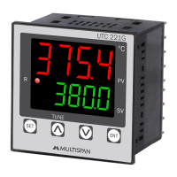
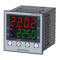
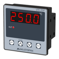
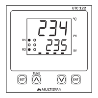
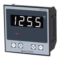
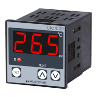
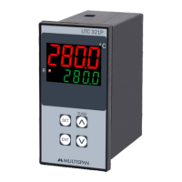
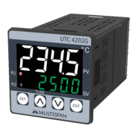
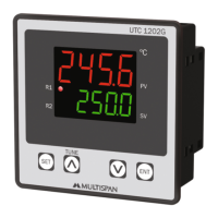
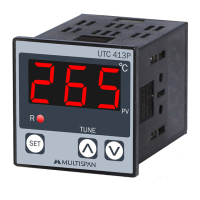
Overview of display segments and key functions.

Dimension

Physical dimensions and panel cutout size.

Control Method

Specifies PID and ON-OFF control for heating and cooling.

Output Specification

Relay Output

Details on relay type, rating, and output signal.

SSR Drive Output

Technical specifications for SSR drive output.

Power Supply

Supply Voltage

Specifies the acceptable supply voltage range.

Power Consumption

Details power consumption in VA rating.

Environment Condition

Operating Temperature and Humidity

Specifies operating temperature and relative humidity limits.

Protection Level

Defines the protection level against dust and water.

Mechanical Installation

Outline Dimension

Visual representation of unit dimensions.

Panel Cutout Dimension

Required panel cutout dimensions for installation.

Terminal Connection

Sensor Input Wiring

Diagram showing sensor input terminal connections.

Relay Output Wiring

Diagram illustrating relay output terminal connections.

SSR Output Wiring

Diagram showing SSR output terminal connections.

Status LED Description

Key Operation

Safety Precaution

Warning Guidelines

Risk of Electric Shock

Precautions to prevent electric shock during wiring and operation.

Installation Guidelines

General Installation Precautions

Guidelines for safe installation, preventing hazards and electrical shock.

Mechanical Installation Guidelines

Panel and Wiring Installation

Steps for fitting the unit into a panel and wiring terminal blocks.

Maintenance

Cleaning and Component Replacement

Instructions for cleaning the equipment and replacing fusible resistors.

Error Display

Error Codes and Meanings

Lists error codes, their meanings, and corrective actions.

Parameter Setting

Set Point Setting

Procedure for setting the process value and set point.

Factory Setting

Procedure to enter and apply factory settings.

Parameter Range

Defines the configurable ranges for various control parameters.

Basic Configuration

Configuration Parameters

Details on setting input, relay mode, control action, hysteresis, and limits.

Control Parameter Setting

PID Control Parameters

Explanation of setting Proportional Band, Integral time, Derivative time, and Manual Reset.

Auto Tuning

Auto Tuning Functionality

Describes how auto-tuning computes and sets PID parameters automatically.

Control Function

ON-OFF Control (Heating)

Illustrates the ON-OFF control behavior for heating.

ON-OFF Control (Cooling)

Illustrates the ON-OFF control behavior with delay time for cooling.

Related product manuals