EasyManua.ls Logo

MULTISPAN UTC-2202 - User Manual

MULTISPAN UTC-2202
8 pages
Print Icon
To Next Page IconTo Next Page
Loading...
PV = Process Value
SV = Set Value
UTC-2202
TEMPERATURE CONTROLLER
TECHNICAL SPECIFICATION
INPUT SPECIFICATION:
Input Types
Resolution
Indication
Accuracy
Input Range
0 to 600°C,
0 to 1200°C,
-99 to 400°C,
-99.9 to 400.0°C,
J
K
PT-100
PT.1
J,K,PT-100 = 1°C
±1% of FSD ± 1°C
PT.1 = 0.1°C
(FSD:-Full Scale Deflection)
DIMENSION :
Size (mm)
Panel Cutout
72 (H) x 72 (W) x 85 (D) mm
68(H) x 68(W) mm
DISPLAY & KEYS :
Display
Key
SET, INC, DEC , ENT
Upper: 4 digit, 7 segment, 0.70” Red
Lower: 4 digit, 7 segment, 0.50” Green
CONTROL METHOD :
Heating
Cooling
Alarm
1) PID control with Auto-Tuning
2) (TP) Time Proportional
(2) ON-OFF control
(1) BL.TP ( Blower Time Proportional)
High/ Absolute Low/Inband/Absolue
Outband/End Alarm
POWER SUPPLY:
Power Consuption
(VA Rating)
Supply Voltage
100 to 270V AC, 50-60Hz
Approx 4VA @ 250V AC MAX
ENVIRONMENT CONDITION:
Relative Humidity
Operating Temp.
0°C to 55°C
UP to 95% RH
(non-condensing)
MECHANICAL INSTALLATION
TERMINAL CONNECTION
Page -1
3) ON-OFF control
OUTPUT SPECIFICATION:
Relay
Output Signal
Relay Type
Rating
2 Nos
12V DC, 30mA DC
(On-Off condition)
Relay 1 parallel to SSR
1C/O (NO-C-NC)
10A, 230V AC / 28V DC
Relay Output
SSR Drive Output
72
85
68
68
3
72
Outline Dimension (mm)
Panel Cutout
Dimension (mm)
SET
ENT
UTC 2202
R1
R2
TUNE
PV
SV
ºC
200.O
200.O
TC
+
RTD
-
!
L
N
1
2
3
4
5
6
7
-
+
O/P
S.S.R
RELAY-1
RELAY-2
100
270V AC
~
50/60 Hz
4VA
NC
NO
NO
NC
C
C
8
9
10
11
12
13
14
Made in India
www.multispanindia.com
Sensor input
8 8
8
10 10
9 9
9
3-Wire RTD 2-Wire RTD
Thermocouple
Install jumper
when using
2 Wire RTD
+
Sensor Input
Question and Answer IconNeed help?

Do you have a question about the MULTISPAN UTC-2202 and is the answer not in the manual?

Summary

TECHNICAL SPECIFICATION

INPUT SPECIFICATION

Details input types, ranges, resolution, and accuracy.

CONTROL METHOD

Lists available control methods like PID, TP, and ON-OFF.

POWER SUPPLY

Details the required supply voltage and power consumption.

OUTPUT SPECIFICATION

Relay and SSR Output

Details specifications for Relay and SSR drive outputs.

MECHANICAL INSTALLATION

Dimensions

Shows outline and panel cutout dimensions of the controller.

ENVIRONMENT CONDITION

Operating Parameters

Specifies operating temperature and relative humidity ranges.

USER INTERFACE AND OPERATION

Key Operation

Explains button functions in operator and parameter setting modes.

SAFETY AND INSTALLATION

Warning Guidelines

Provides critical warnings about electric shock and proper wiring.

Installation Guidelines

Covers general installation, mechanical aspects, and panel mounting.

Safety Precautions

Emphasizes adherence to all safety codifications and instructions.

MAINTENANCE

Cleaning and Safety

Covers cleaning procedures and fusible resistor safety.

FACTORY SETTING

Parameter Values

Lists factory default parameters and their corresponding values.

Parameter Message Description

Explains the meaning of various parameter codes used in the controller.

SOAK TIME FUNCTION

Soak Feature Usage

Explains how to use the soak feature to hold process at preset temperature for a duration.

Soak Time Completion

Describes display indications and restart behavior upon soak time completion.

Soak Time Memory

Details the behavior of soak time counting across power interruptions.

ERROR DISPLAY

Error Codes and Meanings

Lists error codes like OPEN and SrE and their corresponding meanings.

Corrective Action

Provides steps to troubleshoot and resolve detected sensor errors.

PARAMETER SETTING

SET POINT SETTING

Guides on setting Set Point 1 and Set Point 2, including alarm conditions.

CONTROL PARAMETER SETTING

Details setting PID, TP, or BL.TP control parameters.

BASIC CONFIGURATION

Explains configuration of control modes and alarm settings.

CONTROL FUNCTION

ON-OFF Control Modes

Illustrates ON-OFF control behavior for heating and cooling with relay modes.

Auto Tuning Function

Explains how auto-tuning computes and sets PID parameters and its indicator.

Overview

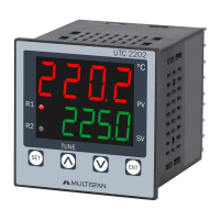
This document describes the AMULTISPAN UTC 2202 Temperature Controller, a device designed for precise temperature regulation in various industrial and commercial applications. The controller features a clear digital display for both process value (PV) and set value (SV), along with intuitive key operations for parameter setting and control.

Function Description

The UTC 2202 is a versatile temperature controller capable of managing heating and cooling processes. It offers multiple control methods to suit different application requirements:

  • PID Control with Auto-Tuning: This is the most advanced control method, allowing the controller to automatically compute and set optimal Proportional Band (Pb), Integral Time (It), Derivative Time (dt), and Cycle Time (Ct) parameters based on the process characteristics. This ensures precise and stable temperature control. The auto-tuning function is initiated by pressing a specific key combination for 6 seconds, and a dedicated LED indicates when auto-tuning is active. If power is interrupted during auto-tuning, the process will restart upon power restoration.
  • Time Proportional (TP) Control: This method provides a simpler form of control by varying the ON/OFF time of the output based on the deviation from the setpoint.
  • ON-OFF Control: This is the most basic control method, where the output is simply switched ON when the temperature is below the setpoint (for heating) or above the setpoint (for cooling), and OFF when the temperature reaches or exceeds the setpoint (for heating) or falls below the setpoint (for cooling). Hysteresis can be configured to prevent rapid cycling of the output.
  • Blower Time Proportional (BL.TP) Control: Specifically designed for cooling applications, this method uses time proportional control for blower operation.

The controller supports various input types, including J, K, and PT-100 thermocouples, and PT.1 RTDs, allowing it to be integrated with a wide range of temperature sensors. It provides two relay outputs and an SSR drive output, offering flexibility in controlling external heating or cooling elements.

Usage Features

The UTC 2202 is designed for ease of use with a straightforward interface:

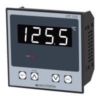
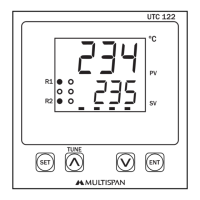
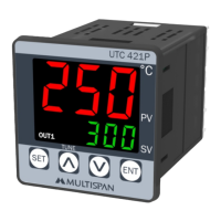
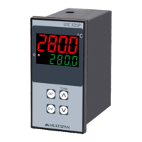
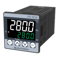
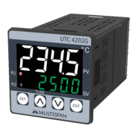
  • Display: The device features a dual 4-digit, 7-segment LED display. The upper display (0.70" Red) shows the Process Value (PV), while the lower display (0.50" Green) shows the Set Value (SV).
  • Key Operation: Three primary keys – SET, INC (increment), and DEC (decrement) – facilitate navigation and parameter adjustment.
    • SET Key: Used to enter parameter setting mode, move to the next parameter, and save/exit settings.
    • INC Key: Used to increment parameter values.
    • DEC Key: Used to decrement parameter values.
    • Combined Key Presses: Specific combinations, such as pressing SET for 6 seconds, are used to start/stop PID auto-tuning. Pressing INC + DEC for 3 seconds allows access to factory setting mode.
  • Status LEDs: Several LEDs provide visual feedback on the controller's status:
    • Soak Time Counting Indication: Indicates when the soak time function is active.
    • Relay 1 Control O/P: Shows the status of Relay 1 output.
    • Relay 2 Control O/P: Shows the status of Relay 2 output.
    • Auto Tuning On Indication: Illuminates when the auto-tuning process is active.
  • Soak Time Function: This feature allows the process to be held at a preset temperature for a specified duration (up to 999 hours). The display indicates when soak time is completed. The controller also includes a soak time memory function, which, if enabled, allows the remaining soak time to continue counting after a power supply failure. If disabled, the soak time counting will restart from the beginning.
  • Alarm Functions: The controller supports various alarm types, including High, Absolute Low, Inband, and Outband alarms, providing critical alerts for process deviations.
  • Parameter Setting: The manual details a comprehensive parameter setting structure, including setpoint settings, control parameters (PB, IT, DT, Cycle Time), and basic configuration settings (input type, control action, alarm types, limits, and password protection).
  • Error Display: The controller provides clear error codes on the display (e.g., "OPEN" for sensor not connected or over-range, "SrE" for reversed sensor connection) to assist in troubleshooting.

Maintenance Features

The UTC 2202 is designed for reliable operation with simple maintenance guidelines:

  • Cleaning: The equipment should be cleaned regularly to prevent blockage of ventilating parts. A clean, soft cloth should be used, and isopropyl alcohol or other cleaning agents are not recommended.
  • Fuse Replacement: The fusible resistor should not be replaced by the operator.
  • Installation Guidelines: Proper installation is crucial for long-term reliability. This includes:
    • Ensuring power supply is OFF during wiring to prevent electric shock.
    • Using adequately rated and twisted wires for connections to minimize electromagnetic interference.
    • Using power supply cables with a cross-section of at least 1mm and insulation capacity of 1.5kV.
    • Installing a circuit breaker or mains switch between the power source and the supply terminal in an easily accessible location.
    • Preventing metal pieces or filings from entering the product during installation.
    • Mounting the unit away from heat sources, caustic vapors, oils, or steam.
    • Using specified crimp terminals (M3.5 screws) and tightening them to a torque of 1.2 N.m.
    • Avoiding connections to unused terminals.
  • Environmental Conditions: The instrument should be used and stored within the specified ambient temperature (0°C to 55°C) and relative humidity (up to 95% RH, non-condensing) ranges to ensure optimal performance and longevity.

MULTISPAN UTC-2202 Specifications

General IconGeneral
Control ModePID, ON/OFF
DisplayDual 4-digit LED
Number of Inputs1
Input TypeThermocouple, RTD
Output TypeRelay, Current
Power Supply100-240 VAC 50/60 Hz
CommunicationRS-485 Modbus RTU

Related product manuals