Do you have a question about the MULTISPAN UTC-421G and is the answer not in the manual?
Details supported input types, their ranges, and resolution.
Information on relay output type, rating, and SSR drive output.
Specifies supply voltage, frequency, and power consumption.
Defines operating temperature and relative humidity limits.
Lists supported heating and cooling control modes.
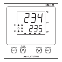
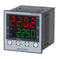
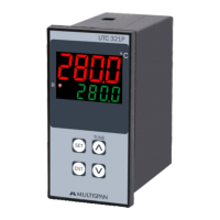
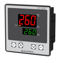
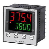
Describes the upper and lower display segments and colors.
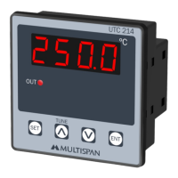
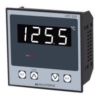
Lists the keys on the controller and their primary functions.
Provides overall unit size and panel cutout dimensions.
Guidelines for fitting the unit into a control panel.
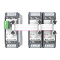
Diagram showing sensor input and power terminal assignments.
Explains the meaning of the status indicator LEDs.
Details how to use the controller's buttons for various functions.
General safety instructions for personnel and instrument.
Specific warnings regarding electrical shock and wiring.
Recommendations for installing the unit within a control panel.
Specifics on panel cutout, terminal use, and wiring.
Instructions for cleaning and care of the instrument.
Codes displayed for sensor connection or range errors.
How to adjust the process value and set point.
Procedures for entering factory settings and applying them.
Defines the configurable range for various parameters.
How to set PID parameters like Proportional Band and Integral time.
Explanation of the automatic tuning process for PID parameters.
Diagram illustrating ON-OFF control logic for heating.
Diagram illustrating ON-OFF control logic for cooling.
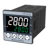
The MULTISPAN UTC-421G is a temperature controller designed for precise temperature management in various applications. Its primary function is to regulate temperature using either PID control with auto-tuning or ON-OFF control methods, supporting both heating and cooling operations.
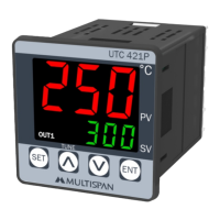
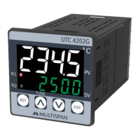
The device features a dual display, showing both the Process Value (PV) and the Set Value (SV). The upper display, with 0.56" digits, indicates the PV, while the lower display, with 0.33" digits, shows the SV. The display color for the upper PV can be either white or red, and the lower SV display is green.
It supports a wide range of input types, including J, J.1, K, K.1, PT-100, and PT.1 thermocouples and RTDs, allowing for temperature measurement across different ranges and resolutions (1°C or 0.1°C). The controller provides a relay output (1 C/O, 10A, 230V AC / 28V DC) and an SSR drive output (12V DC, 30mA DC) for controlling external heating or cooling elements. The relay and SSR outputs operate in parallel.
The control methods include PID control with an auto-tuning function and ON-OFF control. PID auto-tuning automatically calculates and sets the Proportional band (Pb), Integral time (It), Derivative time (dt), and cycle time based on the process characteristics, simplifying setup. During auto-tuning, a dedicated LED indicator turns ON. If power is interrupted during auto-tuning, the process will restart upon power restoration. For ON-OFF control, the device manages heating or cooling by switching the output ON or OFF based on the set value and hysteresis, with an optional delay time for cooling.
The device incorporates several safety features, including an IP-65 rating for the front side, protecting against dust and water ingress. Error codes like "OPEN" (sensor not connected, over range, or sensor break) and "Sr.E" (sensor connection reversed) are displayed to help diagnose issues.
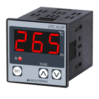
The UTC-421G is designed for ease of use with a straightforward key operation. The front panel includes "TUNE," "SET," and "ENT" buttons, along with increment (▲) and decrement (▼) keys.
The manual provides clear guidelines for installation and maintenance to ensure safe and reliable operation.
The UTC-421G is a robust and user-friendly temperature controller designed for a variety of industrial and commercial applications requiring precise temperature regulation.
| Control Method | PID, On/Off |
|---|---|
| Number of Outputs | 2 |
| Communication | RS-485 Modbus RTU |
| Input Type | Thermocouple, RTD |
| Output Type | Relay, 4-20 mA |
| Display Type | LED |
| Power Supply | 100-240V AC, 50/60Hz, 24V DC |
| Weight | Approximately 150g |