EasyManua.ls Logo

MULTISPAN UTC-421P - User Manual

MULTISPAN UTC-421P
4 pages
Print Icon
To Next Page IconTo Next Page
Loading...
Page 1
UTC-421P
INPUT SPECIFICATION:
PV = Process Value
SV = Set Value
TEMPERATURE CONTROLLER
DISPLAY AND KEYS:
CONTROL METHOD:
DIMENSION:
OUTPUT SPECIFICATION:
POWER SUPPLY:
ENVIRONMENT CONDITION:
Display
Heating
Size
Keys
Cooling
Panel Cutout
Power
Consuption
(VA Rating)
Relative Humidity
Protection Level
(As per request)
Relay
Output Signal
Supply
Voltage
Operating Temp.
Relay Type
Rating
Upper: 3 digit, 7 segment, 0.63”
1) PID control with Auto-Tuning
Lower: 3 digit, 7 segment, 0.30”
3) ON-OFF control
48 (H) x 48 (W) x 70 (D) mm
100 to 270V AC, 50-60Hz
0°C to 55°C
UP to 95% RH
(non-condensing)
IP-65 (Front side) As per IS/IEC
60529 : 2001
1 Nos
12V DC, 30mA DC
(On-Off condition)
1C/O (NO-C-NC)
10A, 230V AC / 28V DC
SET, INC, DEC, ENT
ON-OFF control
45 (H) x 45 (W) mm
4VA @ 230V AC MAX
Relay Output
SSR Drive Output
TECHNICAL SPECIFICATION
70
45
45
3
MECHANICAL INSTALLATION
TERMINAL CONNECTION
Outline Dimension (mm)
Panel Cutout
Dimension (mm)
6 6
6
8 8
7 7
7
3-Wire RTD 2-Wire RTD
Thermocouple
Install jumper
when using
2 Wire RTD
Sensor input
+
www.multispanindia.com
Made in India
T/C
+
+
RTD
-
-
NC
C
R1
NO
O/P
SSR
!
100
270V AC
1
2
3
4
5
L
N
6
7
8
9
10
~
50/60 HZ
4VA
Sensor Input
2) (TP) Time Proportional
48
48
Display Color:
Upper : RED/WHITE
Lower: Green
SV
PV
SET ENT
UTC 421P
°
OUT1
TUNE
Input Types
Resolution
Indication
Accuracy
Input Range
0 to 600°C,
0 to 999°C,
-99 to 400°C,
J
K
PT-100
J,K,PT-100 = 1°C
±1% of FSD ± 1°C
(FSD:-Full Scale Deflection)
-19.9 to 99.9°C,
PT.1
PT.1 = 0.1°C
Question and Answer IconNeed help?

Do you have a question about the MULTISPAN UTC-421P and is the answer not in the manual?

Summary

Power Supply and Environmental Conditions

Power Supply Details

Specifies supply voltage, frequency, and power consumption.

Environmental Operating Parameters

Defines operating temperature, humidity, and protection level.

Technical Specifications Overview

Input and Signal Characteristics

Details supported input types, ranges, accuracy, and resolution.

Control and Output Functions

Covers control methods (PID, ON-OFF) and output types (Relay, SSR).

Physical and Installation Guidelines

Unit Dimensions and Panel Cutout

Provides outline dimensions and required panel cutout size.

Terminal Connection Diagram

Illustrates wiring for power supply and sensor inputs.

Safety and Warning Guidelines

Risk of Electric Shock Precautions

Instructions to prevent electric shock during wiring and operation.

Installation Safety Warnings

Guidance on safe installation practices and avoiding hazards.

Operation and Parameter Setting

Error Display and Correction

Explains error codes and corrective actions for sensor issues.

Parameter Setting Modes

Details on setting parameters, factory settings, and ranges.

Control Functions and Auto-Tuning

ON-OFF Control Modes

Illustrates ON-OFF control for heating and cooling.

Auto-Tuning Functionality

Explains automatic computation of PID parameters.

Overview

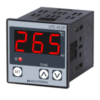
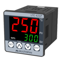
This document describes the Multispan UTC-421P Temperature Controller, a built-in type device designed for precise temperature regulation in various industrial applications.

Function Description

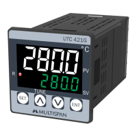
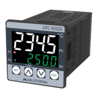
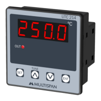
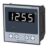
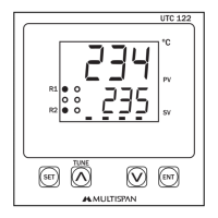
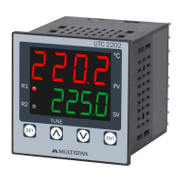
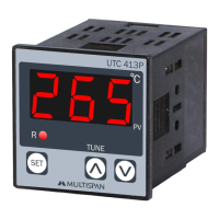
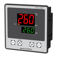
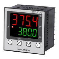
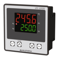
The UTC-421P is a temperature controller that accepts multiple input types, including J and K type thermocouples, as well as PT-100 and PT.1 RTD sensors. It features a dual-display system, with the upper display showing the Process Value (PV) in red/white and the lower display showing the Set Value (SV) in green. The controller offers a high degree of accuracy, with an indication accuracy of ±1% of Full Scale Deflection (FSD) ± 1°C.

The device supports various control methods to suit different process requirements. These include PID control with an auto-tuning function, Time Proportional (TP) control, and ON-OFF control for both heating and cooling applications. The auto-tuning feature automatically calculates and sets optimal PID parameters (Proportional band, Integral time, Derivative time, and cycle time) based on the process characteristics, simplifying setup and ensuring efficient control. If power is interrupted during auto-tuning, the process will restart upon power restoration.

For output, the UTC-421P provides a relay output (1 C/O type, rated 10A at 230V AC or 28V DC) and an SSR drive output (12V DC, 30mA DC) for ON-OFF conditions.

Usage Features

The controller's interface is designed for ease of use, featuring a clear 3-digit, 7-segment display for both PV and SV. Navigation and parameter adjustments are managed through dedicated keys: SET, INC (increment), DEC (decrement), and ENT (enter).

  • Operator Mode:

    • To enter parameter setting mode, press the SET key.
    • To start or stop PID auto-tuning, press the INC and DEC keys simultaneously for 6 seconds.
    • To access factory setting mode, press the INC and DEC keys simultaneously for 3 seconds.
  • Parameter Setting Mode:

    • Parameters can be set by pressing the SET key.
    • Values are incremented using the INC key and decremented using the DEC key.
    • To save the set parameter value and exit, press the ENT key.
  • Set Point Setting: The device allows users to set a desired temperature (Set Value). Accessing this requires pressing the SET key for 3 seconds to enter a password.

  • Basic Configuration: A password-protected basic configuration menu allows users to define critical settings such as input type (J, K, PT-100, PT.1), output type (SSR, Relay, Both), output mode (Heat/Cool), control action (ON-OFF, PID, TP), hysteresis, time delay, set low limit, set high limit, and offset.

  • Control Parameter Setting: This section, also password-protected, allows for detailed configuration of PID parameters (Proportional Band, Integral Time, Derivative Time, Cycle Time, Manual Reset) or TP parameters (Proportional Band, Cycle Time, Manual Reset), depending on the selected control action.

  • Error Display: The controller provides clear error codes for common issues:

    • "OPn" indicates a sensor not connected, an over-range condition, or a sensor break.
    • "SrE" indicates a reversed sensor connection.
    • Corrective action involves checking the sensor and input wiring; if the problem persists, sensor replacement or contacting customer support is recommended.

Maintenance Features

The UTC-421P is designed for durability and ease of maintenance:

  • Cleaning: The equipment should be cleaned regularly to prevent blockage of ventilating parts. A clean, soft cloth should be used; isopropyl alcohol or other cleaning agents are not recommended.
  • Fuse: The fusible resistor should not be replaced by the operator.

Safety Precautions and Installation Guidelines

  • Electrical Safety: Always turn off the power supply before wiring to prevent electric shock. Do not touch terminals while power is supplied.
  • Wiring: Use adequately rated and twisted wires for shortest connections to reduce electromagnetic interference. Power source cables should have a cross-section of 1mm² or greater and insulation capacity of at least 1.5kV. When extending thermocouple leads, use compensation wires. For RTD types, use wiring material with low lead resistance (5 Ω max per line) and no resistance differentials among the three wires.
  • Installation: The device is a built-in type and typically becomes part of a main control panel. Ensure terminals are not accessible to end-users after installation. Prevent metal pieces, wire clippings, or fine metallic fillings from entering the product. A circuit breaker or mains switch must be installed between the power source and supply terminal, placed conveniently for operator access.
  • Environment: Operate and store the instrument within the specified ambient temperature and humidity ranges. Avoid proximity to heating sources, caustic vapors, oil steam, or other unwanted process byproducts.
  • Mounting: Prepare a panel cutout with the specified dimensions (45mm H x 45mm W) and fit the unit using the provided clamp. Use crimp terminals (M3.5 screws) for wiring the terminal block, tightening screws with a torque of 1.2 N.m. Do not connect anything to unused terminals.

This comprehensive design ensures reliable performance, user-friendly operation, and safe integration into various temperature control systems.

MULTISPAN UTC-421P Specifications

General IconGeneral
Input TypeThermocouple, RTD
Control ModePID, On/Off
Number of Outputs2
MountingPanel Mount
OutputRelay, SSR
Power Supply100-240V AC
DisplayLED
Dimensions48 x 48 mm

Related product manuals