EasyManua.ls Logo

MULTISPAN UTC-121P User Manual

MULTISPAN UTC-121P
4 pages
To Next Page IconTo Next Page
Page #1 background imageLoading...
Page #1 background image
ENT
SET
UTC 121
PV
SV
ºC
TC
+
-
+
SSR
O/P
RTD
6
7
8
9
10
-
1
2
3
4
5
NC
C
R1
NO
L
N
!
100
250V AC
50/60 HZ
4VA
~
!
100
250V AC
50/60 Hz
4VA
~
TC
+
RTD
-
!
L
N
1
2
3
4
5
6
7
-
+
O/P
S.S.R
RELAY1
100
250V AC
~
50/60 Hz
4VA
NC
NO
C
8
9
10
11
12
13
14
1
7 8 9
12
1314
10
11
1617181920
15
2
3
4
5
6
NC
C
NO
TC
+
-
+
-
RELAY
100
250V AC
~
50/60 Hz
4VA
!
L
N
O/P
S.S.R
RTD
www.multispanindia.com
Page - 1
UTC-121,221,421
POWER ON POWER ON
8 8 8 8. . . .
j
0 1 2 3
0 1 2 3
8 8 8 8. . . .
I N P t
All digit segment will be turned ON for 3 sec
Previous or default sensor input will be displayed for 2 sec
Process Value
Set Value
j
0 1 2 3
0 1 2 3
I N P t
8
8
8
8
88
8
8
Note:
1) If Sensor Connection is reversed, Display will show message.
2) If Sensor is not connected, Display will show message.
SRE
Open
3) Every time the instrument is turned ON, Following pattern will be displayed
J: 0 to 600°C / K: 0 to 1200°C /
PT-100: -99 to 400ºC /PT.1: -99.0 to 400.0°C
TP / ON-OFF (selectable)
Output
Power Supply
Protection Level
Operating
Relative
(As per request)
Temperature
Humidity
1 relay, 1 C/O contact, 230V AC, 5A ; 1 SSR,12V DC, 30mA DC
100 to 250V AC, 50 / 60 Hz, Approx 4VA
IP-65(Front side) AS per IS/IEC 60529:2001
0°C To 55°C
Up to 95% RH Non Condensing
Model
Display
Size(HXWXD)
Panel Cutout
Input
Temperature
Range
Control Action
UTC 121
96 X 96 X 50 mm
92 X 92 mm
68 X 68 mm
44 X 44 mm
72 X 72 X 85 mm
48 X 48 X 95 mm
UPPER:- 4 Digit 7 seg 0.56”,red LED Display
UPPER:- 4 Digit 7 seg 0.39”,red LED Display
LOWER:- 4 Digit 7 seg 0.4”,green LED Display
LOWER:- 4 Digit 7 seg 0.28”,green LED Display
UTC 221 UTC 421
J, K, PT-100 (selectable)
Technical Specification
Connection Diagram
OPERATING MANUAL
PID TEMPERATURE CONTROLLER
UTC-121P,221P & 421P
1 2 3 4
Technical Specification
Connection Diagram
OPERATING MANUAL
TEMPERATURE CONTROLLER
UTC-121, 221 & 421
R
UTC 421
1 2 3 4
ENT
SET
R1
PV
SV
UTC 221
ºC
0 1 2 3
0 1 2 3
0 1 2 3
0 1 2 3

Other manuals for MULTISPAN UTC-121P

Question and Answer IconNeed help?

Do you have a question about the MULTISPAN UTC-121P and is the answer not in the manual?

MULTISPAN UTC-121P Specifications

General IconGeneral
Input TypeThermocouple, RTD
Display TypeLED
Accuracy±0.3% of full scale
Control ModePID, ON/OFF
Number of Alarms2
MountingPanel mount
Control OutputRelay, SSR
Power Supply100-240 VAC
Temperature RangeDepends on sensor type
Dimensions48 x 48 mm

Summary

Technical Specification

Model UTC 121 Specifications

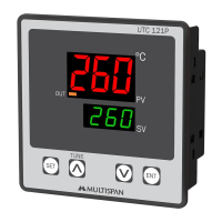
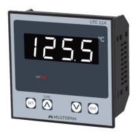
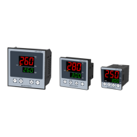
Details for UTC 121: Display, Size, Panel Cutout, Input, Range, Control Action, Output, Power Supply, Protection Level, Operating Temperature.

Model UTC 221 Specifications

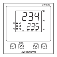
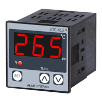
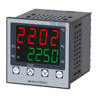
Details for UTC 221: Display, Size, Panel Cutout, Input, Range, Control Action, Output, Power Supply, Protection Level, Operating Temperature.

Model UTC 421 Specifications

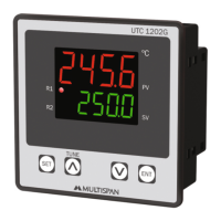
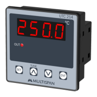
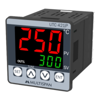
Details for UTC 421: Display, Size, Panel Cutout, Input, Range, Control Action, Output, Power Supply, Protection Level, Operating Temperature.

Operating Notes

Important operational notes regarding sensor connection and power-on display patterns.

Connection Diagram

Wiring for UTC Series Controllers

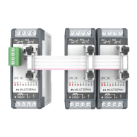
Illustrates wiring connections for TC, RTD, and SSR outputs for the UTC controllers.

Key Operation

Button Functions

Explains the function of SET, UP, DOWN, and ENT keys for navigation and saving.

Basic Configuration

Accessing Basic Configuration

Procedure to enter basic configuration settings by entering '73' as a password.

Input Type Selection

Guide for selecting input type (J/K/Pt.1/Pt100) and setting OFF-SET.

Setting Limits and Control Action

Configuration of Set Point Low Limit (5LL), High Limit (5HL), and Control Action (TP/ON-OFF).

Set Point Setting

Setting the Desired Value

Procedure to set the desired temperature value (SET VALUE) for the controller.

Control Parameter

Accessing Control Parameters

Procedure to enter control parameter settings by entering '37' as a password.

Proportional Band (PB) and Cycle Time (CT)

Setting Proportional Band and Cycle Time for Heat or Cool mode.

Hysteresis and Delay Time

Configuration of Hysteresis and Delay Time for temperature control.

Factory Setting

Applying Factory Default Values

Instructions on how to apply factory set values for parameters like PB, CT, MR, OFFSET, HYSTERESIS, and DELAY TIME.

Safety Precautions

General Safety Guidelines

Adherence to manual instructions for safe operation and personnel safety.

Electrical Shock Warnings

Precautions to prevent electric shock during wiring and operation.

Installation Guidelines

Wiring and Cable Specifications

Guidelines for using adequate wire rating, twists, and specified cross-section for connections.

Panel Mount Installation

Instructions for preparing panel cutouts and fitting the unit securely.

Environmental Considerations

Advice on avoiding proximity to heating sources and caustic vapors during installation.

Maintenance

Cleaning and Care

Recommendations for regular cleaning with a soft cloth and avoiding specific cleaning agents.

Related product manuals