Do you have a question about the MULTISPAN UTC-113P and is the answer not in the manual?
General safety related codifications, symbols, and instructions for safe operation.
Specific warnings regarding electric shock, wiring, interference, and noise reduction.
Instructions for installing built-in type equipment, avoiding hazards like metal debris.
Panel cutout dimensions, unit fitting, proximity to heat/vapors, and terminal wiring torque.
Describes basic key functions like setting, changing values, saving, and entering modes.
Instructions for setting the process value and initiating PID auto-tuning.
Procedure to access and apply factory default parameter values.
Entering the basic configuration mode with a password.
Setting various control parameters like PID, input, offset, limits, and action.
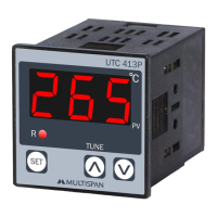
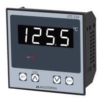
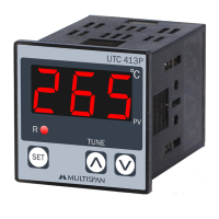
This document outlines the operation, installation, and maintenance procedures for the Multispan PID Temperature Controller, available in UTC-113P, 213P, and 413P models. These devices are designed for precise temperature regulation in various industrial applications.
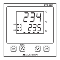
The PID Temperature Controller functions by continuously monitoring a process variable (PV), which is the current temperature, and comparing it to a desired set point (SP). Based on this comparison, it calculates and applies a control output to maintain the temperature at the set point. The controller supports both PID (Proportional-Integral-Derivative) and ON-OFF control actions, offering flexibility for different process requirements. PID control provides a more refined and stable temperature regulation by adjusting the output based on the error, the accumulation of past errors, and the rate of change of the error. ON-OFF control, on the other hand, is a simpler method where the output is either fully on or fully off, typically used for less critical applications or where precise control is not paramount.
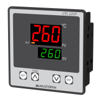
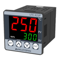
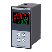
The device features a 3-digit, 7-segment, 0.56-inch red LED display, which clearly shows the process value. Upon power-on, the display undergoes a brief segment test, showing "888" for 3 seconds, followed by a "---" for 2 seconds, before displaying the current process value. This sequence ensures all display segments are functional. The controller accepts various input types, including J-type and K-type thermocouples, and PT-100 RTD sensors, making it adaptable to a wide range of temperature sensing applications. The temperature range varies depending on the sensor type: 0 to 600°C for J-type, 0 to 999°C for K-type, and -99 to 400°C for PT-100.
Key operational features include intuitive parameter setting and an auto-tuning function. Users can access various settings by pressing the "SET" key. Parameters can be adjusted using the "UP" and "DOWN" arrow keys, and changes are saved by pressing "SET" and "UP" simultaneously. The auto-tuning feature, activated by holding the "SET" key for 6 seconds, automatically calculates optimal PID parameters (Proportional Band, Integral Time, Derivative Time) for a given process, simplifying setup and ensuring efficient control. This eliminates the need for manual tuning, which can be time-consuming and require specialized knowledge.
The controller's configuration is divided into "Basic Configuration" and "Control Parameter" sections, each protected by a password to prevent unauthorized changes. The Basic Configuration, accessed with password "73," allows users to select the input sensor type (J, K, or PT-100) and set an offset value to compensate for any sensor inaccuracies. It also enables setting the Set Point Low Limit (SLL) and Set Point High Limit (SHL), defining the permissible range for the set point. The Control Parameter section, accessed with password "37," is where the core control logic is defined. Here, users can select between PID and ON-OFF control actions. If PID is selected, parameters such as Proportional Band (Pb), Integral Time (It), Derivative Time (dt), and Cycle Time (Ct) can be adjusted. A Manual Reset (Mr) option is also available for fine-tuning. For ON-OFF control, the hysteresis (HYS) and delay time (dLY) can be configured. Hysteresis prevents rapid cycling of the output around the set point, while delay time introduces a brief pause before the output changes state, protecting connected equipment.
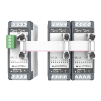
The device incorporates safety features and guidelines to ensure reliable and secure operation. It is designed as a built-in type, intended to be integrated into a main control panel, with terminals becoming inaccessible after installation. This design minimizes the risk of accidental contact with live parts. The manual emphasizes the importance of following all safety codes and instructions, particularly regarding electrical shock prevention. Power supply to the equipment must be disconnected during wiring, and terminals should not be touched while power is supplied. Proper wiring practices, including using adequately rated and twisted wires with shortest connections, are recommended to reduce electromagnetic interference. The use of specific compensation wires for thermocouples and wiring material with low lead resistance for RTDs is crucial for accurate temperature measurement.
Installation guidelines detail the mechanical mounting process, which involves preparing a panel cutout of specified dimensions and securing the unit with clamps. It is crucial to ensure the equipment is not installed near heating sources, caustic vapors, oils, or steam, which could affect its performance or lifespan. The use of specified crimp terminals and appropriate tightening torque for terminal block screws is also highlighted to ensure secure electrical connections.
Maintenance procedures are straightforward, focusing on keeping the equipment clean to prevent blockage of ventilating parts. Cleaning should be done with a soft cloth, avoiding isopropyl alcohol or other harsh cleaning agents. Users are explicitly warned not to replace the fusible resistor, as this component is critical for safety and should only be serviced by qualified personnel.
Error messages provide immediate feedback on potential issues. "SrE" indicates a reversed sensor connection, while "OPn" signifies an open or disconnected sensor. These messages help in quick troubleshooting.
In summary, the Multispan PID Temperature Controller offers a robust and versatile solution for temperature control, combining precise regulation capabilities with user-friendly operation and comprehensive safety features. Its adaptability to various sensor types, auto-tuning function, and clear display make it suitable for a wide array of industrial applications requiring accurate and stable temperature management.
| Control Mode | PID, On/Off |
|---|---|
| Number of Inputs | 1 |
| Operating Temperature | 0-50°C |
| Input Type | Thermocouple, RTD |
| Output Type | Relay, SSR |
| Display | 4-digit LED Display |
| Power Supply | 100-240VAC 50/60Hz |