Do you have a question about the MULTISPAN UTC-214 and is the answer not in the manual?
Details about input types, range, resolution, and accuracy.
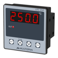
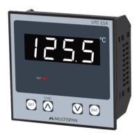
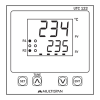
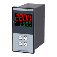
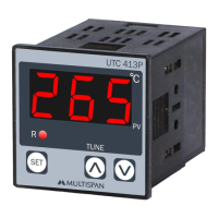
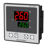
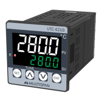
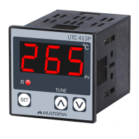
Information on the display type and the control keys available.
Physical size and panel cutout dimensions of the controller.
Describes the available control actions like PID, TP, and ON-OFF.
Details on relay output type, rating, and SSR drive output.
Specifies the external physical dimensions of the controller unit.
Provides the required dimensions for panel mounting.
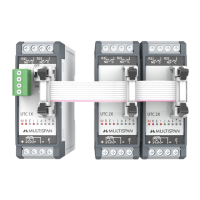
Diagram illustrating wiring for sensors, power, and output.
Explains the meaning of the controller's status indicator LEDs.
Details how to use the physical keys for various functions and modes.
Important safety instructions to follow during operation and handling.
Critical warnings regarding electric shock and interference.
Recommendations for safe and correct installation practices.
Procedures for cleaning and maintaining the controller.
Settings related to input, output, and control action.
Configuration for PID, integral time, derivative time, and hysteresis.
Table outlining the valid range for each configurable parameter.
Identifies error codes and provides steps for resolution.
Steps to restore the controller to its default factory settings.
How to adjust the desired process value or set point.
Illustrates ON-OFF control behavior for heating and cooling.
Explanation of the auto-tuning process for PID parameter calculation.
The Multispan UTC-214 is a temperature controller designed for precise temperature management in various industrial applications. It offers a range of control methods and input types, making it a versatile solution for heating and cooling processes.
The UTC-214 primarily functions as a temperature controller, capable of maintaining a desired temperature setpoint through various control actions. It supports PID control with auto-tuning, time proportional (TP) control, and ON-OFF control for both heating and cooling applications. The device accepts multiple input types, including J, K, PT-100, and PT.1 thermocouples and RTDs, allowing it to interface with a wide array of temperature sensors. It features a clear 4-digit, 7-segment red LED display for process value and setpoint indication, along with status LEDs for control output (OUT) and auto-tune (AT) indication. The controller provides a relay output (1C/O) for switching external loads and an SSR drive output for solid-state relay control.
The Multispan UTC-214 is a robust and reliable temperature controller designed for industrial environments, offering precise control, ease of use, and essential safety features.
| Brand | MULTISPAN |
|---|---|
| Model | UTC-214 |
| Category | Temperature Controller |
| Language | English |