EasyManua.ls Logo

MULTISPAN UTC - 413P User Manual

MULTISPAN UTC - 413P
2 pages
To Next Page IconTo Next Page
Page #1 background imageLoading...
Page #1 background image
www.multispanindia.com
Page - 1
UTC-413P
Note:
1) If Sensor Connection is reversed, Display will show “SRE” message.
2) If Sensor is not connected, Display will show Opn message.
3) Every time the instrument is turned ON, Following pattern will be displayed
J: 0 to 600°C / K: 0 to 999°C /
PT-100: -99 to 400ºC
PID / ON-OFF (selectable)
Output
Power Supply
Operating
Relative
Protection Level
(As per request)
Temperature
Humidity
1 relay, 1 C/O contact, 230V AC, 5A ; 1 SSR,12V DC Approx, 30mA DC
100 to 270V AC, 50 / 60 Hz, Approx 4VA
IP-65(Front side) AS per IS/IEC 60529:2001
0°C To 55°C
Up to 95% RH Non Condensing
Display
Size(HXWXD)
Panel Cutout(HxW)
Input
Temperature
Range
Control Action
45 X 45 mm
48 X 48 X 70 mm
3 Digit 7 seg 0.56”,red LED Display
J, K, PT-100 (selectable)
Technical Specification
Connection Diagram
OPERATING MANUAL
PID TEMPERATURE CONTROLLER
UTC - 413P
1 2 3
UTC 413P
POWER ON
All digit segment will be turned ON for 3 sec
Previous or default sensor input will be display for 2 sec
Process Value
8 88
- J -
1 2 3
www.multispanindia.com
Page - 2
All safety related codifications, symbols and instructions that appear in this operating manual
or on the equipment must be strictly followed to ensure the safety of the operating personnel as
well as the instrument.
If all the equipment is not handled in a manner specified by the manufacturer, it might impair the
protection provided by the equipment .
Product improvement and upgrade is a constant procedure. So for more updated operating information and support,
Please contact our helpline : +91-9978991476/9978991474/9978991482 or Email at service@multispanindia.com Ver: 2102
=> Read complete instructions prior to installation and operation of the unit.
WARNING : Risk of electric shock.
3) Cable used for connection to power source, must have a cross section of 1mm or greater. These wires
should have insulations capacity made of at least 1.5kV.
2) To reduce electro magnetic interference, use wire with adequate rating and twists of the same of equal size shall
be made with shortest connection.
4) When extending the thermocouple lead wires, always use thermocouple compensation wires for wiring for the RTD
type, use a wiring material with a small lead resistance (5Ω max per line)and no resistance differentials among
three wires should be present.
1) To prevent the risk of electric shock power supply to the equipment must be kept OFF while doing the wiring
arrangement. Do not touch the terminals while power is being supplied.
5) A better anti-noise effect can be expected by using standard power supply cable for the instrument.
1) This equipment, being built-in-type, normally becomes a part of main control panel and such in case the
terminals do not remain accessible to the end user after installation and internal wiring.
2) Do not allow pieces of metal, wire clippings, or fine metallic fillings from installation to enter the product
or else it may lead to a safety hazard that may in turn endanger life or cause electrical shock to the operator.
3) Circuit breaker or mains switch must be installed between power source and supply terminal to
facilitate power ‘ON’ or ‘OFF’ function. However this mains switch or circuit breaker must be
installed at convenient place normally accessible to the operator.
4) Use and store the instrument within the specified ambient temperature and humidity ranges as
mentioned in this manual.
Warning Guidelines
Safety Precautions
Installation Guidelines
Mechanical Installation
Maintenance
1) Prepare the panel cutout with proper dimensions as show above.
2) Fit the unit into the panel with the help of clamp given.
3) The equipment in its installed state must not come in close proximity to any heating source,
caustic vapors, oils steam, or other unwanted process by products.
4) Use the specified size of crimp terminal (M3.5 screws) to wire the terminal block. Tightening the
screws on the terminal block using the tightening torque of the range of 1.2 N.m.
5) Do not connect anything to unused terminals.
1) The equipment should be cleaned regularly to avoid blockage of ventilating parts.
2) Clean the equipment with a clean soft cloth. Do not use isopropyl alcohol or any other cleaning agent.
3) Fusible resistor must not be replaced by operator.
2
UTC-413P
1 2 3
UTC 413P
48
70
45
45
3
48
Outline Dimension (mm)
Panel Cutout
Dimension (mm)
TC
+
-
+
SSR
O/P
RTD
6
7
8
9
10
-
1
2
3
4
5
NC
C
R1
NO
L
!
100
250V AC
50/60 HZ
4VA
~
!
100
270V AC
50/60 Hz
4VA
~
N
Made in India
www.multispanindia.com
Question and Answer IconNeed help?

Do you have a question about the MULTISPAN UTC - 413P and is the answer not in the manual?

MULTISPAN UTC - 413P Specifications

General IconGeneral
Input TypeThermocouple, RTD
Number of Inputs1
Control ModePID, On/Off
MountingPanel Mount
OutputRelay
Power Supply100-240 VAC
DisplayLED
CommunicationRS485 Modbus
Control Output Current3A

Summary

Technical Specification

Display

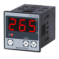
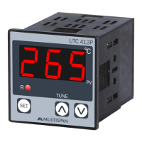
3 Digit 7 seg 0.56", red LED Display.

Size and Panel Cutout

Unit dimensions 48x48x70mm, panel cutout 45x45mm.

Input and Range

Selectable J, K, PT-100 sensors with specific temperature ranges.

Control Action and Output

PID/ON-OFF selectable control with relay and SSR outputs.

Power Supply and Environment

100-270V AC power, IP-65 front, 0-55°C operating temp, 95% RH.

Safety Precautions

General Safety Instructions

Follow all safety codifications, symbols, and instructions for safe operation.

Electric Shock Warning

Risk of electric shock; ensure power is OFF before wiring.

Warning Guidelines for Wiring

Power Supply Interruption

Keep power OFF during wiring; do not touch terminals when power is supplied.

Electromagnetic Interference Reduction

Use adequate rated wires with twists for shortest connections to reduce EMI.

Power Cable Specifications

Use 1mm² or greater cross-section cables with at least 1.5kV insulation.

Thermocouple and RTD Lead Wire

Use compensation wires for thermocouples and low-resistance wires for RTDs.

Anti-Noise Effect

Standard power supply cables improve anti-noise effect.

Installation Guidelines

Panel Mounting and Accessibility

Built-in type installation; terminals may not be accessible post-installation.

Preventing Foreign Material Entry

Avoid metal pieces or debris entering the product to prevent safety hazards.

Circuit Breaker Requirement

Install a circuit breaker or mains switch for power ON/OFF control.

Operating Environment

Use and store the instrument within specified ambient temperature and humidity.

Mechanical Installation

Panel Cutout and Mounting

Prepare panel cutout as shown and fit unit using clamps.

Proximity to Heat Sources

Avoid installing near heating sources, caustic vapors, or steam.

Terminal Wiring Torque

Use M3.5 crimp terminals and tighten screws to 1.2 N.m.

Unused Terminals

Do not connect anything to unused terminals.

Maintenance

Cleaning Procedure

Clean regularly with a soft cloth; avoid isopropyl alcohol or other agents.

Fusible Resistor Replacement

Fusible resistor must not be replaced by the operator.

Key Operation

Parameter Setting Navigation

Use SET, UP, DOWN keys for parameter setting and saving.

Auto-Tuning Activation

Press UP key for 6 seconds to start or stop PID auto-tuning.

Factory Setting Mode

Press UP + DOWN keys for 3 seconds to enter factory setting mode.

Set Point Setting

Entering Password

Press SET key for 3 seconds to enter password parameter.

Password Entry

Enter password '050' to proceed to basic configuration.

Basic Configuration

Accessing Configuration

Enter '73' to access basic configuration settings.

Input Type Selection

Select input type (J, K, PT-100) using UP/DOWN keys.

Offset Setting

Set the offset value for the input sensor.

Set Point Limits

Configure Set Point Low Limit (SLL) and Set Point High Limit (SHL).

Control Action Selection

Choose between PID and ON-OFF control actions.

Relay Mode

Select Relay Mode (HE for Heat, COL for Cool).

Control Parameter

Accessing Control Parameters

Enter '37' to access control parameter settings.

PID Tuning Parameters

Configure Proportional Band (PB), Integral Time (IT), Derivative Time (DT).

Cycle Time and Manual Reset

Set Cycle Time (CT) and adjust Manual Reset (MR).

Hysteresis and Delay Time

Configure Hysteresis and Delay Time for control output.

Factory Setting

Accessing Factory Settings

Press UP + DOWN keys for 3 seconds to enter factory setting mode.

Applying Factory Defaults

Use UP + DOWN keys to apply factory set values or escape.

Default Parameter Values

Table lists default SR, Parameter (PB, IT, DT, CT, MR, OFFSET, HYSTERESIS, DELAY TIME) and Values.

Related product manuals