Do you have a question about the MULTISPAN PTC-1202A and is the answer not in the manual?
Details supported sensor inputs like J, K, PT-100 and their respective measurement ranges.
Specifies the instrument's indication accuracy and display resolution.
Information on relay type, rating, and analog output specifications.
Covers supply voltage, power consumption, and operating conditions.
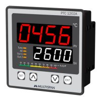
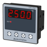
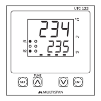
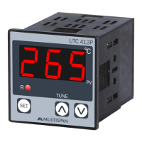
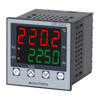
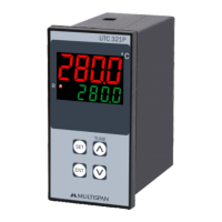
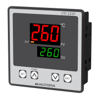
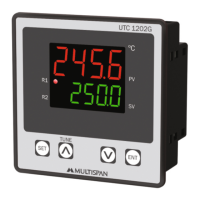
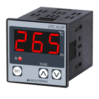
Describes the unit's display, control buttons, and physical size.
Lists control options (Heating, Cooling, Alarm) and terminal connections.
Instructions for accessing parameter setting, auto-tuning, and factory reset.
Details on modifying parameter values using the control keys.
Guidelines for panel cutout, unit fitting, and terminal wiring.
Emphasizes adherence to safety codes and warnings for safe operation.
Specific warnings regarding the risk of electric shock during wiring.
Instructions for cleaning the unit and maintaining ventilation.
Advice on reducing electromagnetic interference and using proper wiring.
Procedure for accessing and applying factory default settings.
Explanation of various parameter codes and their meanings.
Defines the valid input ranges for control parameters.
Further explanation of parameter codes like LOPC, HI PC, Frud, etc.
Steps for configuring analog output and controlling modes.
Explanation of password entry and basic configuration parameter.
Configuration details for Relay 1 and Relay 2 in Heat, Cool, and Alarm modes.
Details on parameters related to input selection and basic configuration.
Steps for setting up analog output parameters like PU/SU/CON.
Configuration options for the soak timer function.
Graphical explanations of High, Low, Outband, and Inband alarm behaviors.
The Multispan PTC-1202A is a process and temperature controller designed for industrial applications, offering precise control and monitoring capabilities.
The device functions as a PID (Proportional-Integral-Derivative) controller, capable of both PID control with auto-tuning and ON-OFF control for heating and cooling applications. It also supports blower time proportion (BL.TP) for cooling. The controller features two relay outputs for control actions and an analog output (4-20mA DC) for retransmission of process value (PV) or set value (SV), or for manual selection. It includes alarm functions such as High, Low, Inband, Outband, Absolute Low, and Absolute Outband alarms. A soak timer function is also available, allowing for programmed temperature profiles.
The controller is designed for ease of use with a clear display and intuitive key operations.
SET key: Used to enter parameter setting mode (press for 5 seconds), set parameter values, and save/exit parameter settings.V key: Used to increment parameter values.^ key: Used to decrement parameter values.ENT key: Used to enter parameter setting mode, start/stop PID auto-tuning (press for 6 seconds), go to factory setting mode (press for 3 seconds), and reset soak process (long press).The device is designed for minimal maintenance, with clear guidelines for installation and cleaning.
| Brand | MULTISPAN |
|---|---|
| Model | PTC-1202A |
| Category | Temperature Controller |
| Language | English |