Do you have a question about the MULTISPAN TC-49 and is the answer not in the manual?
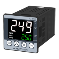
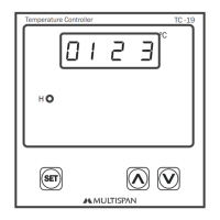
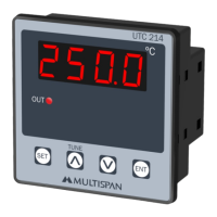
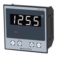
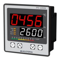
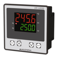
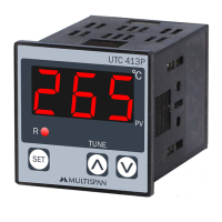
Details the controller model and its 3-digit LED display specifications.
Specifies the controller's overall size and panel cutout dimensions.
Defines supported thermocouple input types (J, K) and their temperature ranges.
Details the selectable control action and available output types and ratings.
Specifies power supply requirements and ingress protection level (IP-65).
Defines the acceptable operating temperature and relative humidity ranges.
Error messages for incorrect or disconnected sensor connections.
Instructions for viewing set points and details on auto-save time.
Describes the display pattern shown immediately after powering on the instrument.
General instructions for using device keys to set parameters.
Procedure for setting and saving the desired temperature set point.
Instructions to enter basic configuration by inputting a password.
Configuration option to select the thermocouple input type (J or K).
Setting the control action mode (e.g., ON-OFF, TP, EP).
Procedure for setting the offset correction value within a specified range.
Instructions to enter control parameter settings by inputting a password.
Settings for Proportional Band, Cycle Time, and Manual Reset when TP is selected.
Settings for Hysteresis when ON-OFF control action is selected.
Table detailing the configurable parameters and their ranges for J/K inputs.
Emphasizes following all safety codifications and instructions for safe operation.
Highlights the risk of electric shock and precautions during wiring.
Recommendations for wiring, cable selection, and anti-noise measures.
Precautions during installation, including avoiding metal debris and using circuit breakers.
Instructions for preparing panel cutouts and fitting the unit securely.
Guidance on placement relative to heat sources, vapors, and proper terminal wiring.
Recommendations for cleaning the equipment and caution regarding fusible resistors.
| Control Mode | PID, On/Off |
|---|---|
| Mounting | Panel Mount |
| Input | Thermocouple, RTD |
| Output | Relay, SSR drive, 4-20mA |
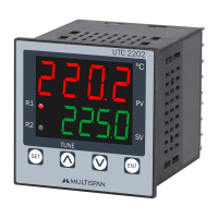
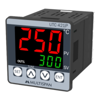
| Display | Dual 4-digit LED |
| Power Supply | AC 100-240V, 50/60Hz |
| Dimensions | 48 x 48 mm |