Do you have a question about the MULTISPAN TC-443 and is the answer not in the manual?
Specifies the voltage range for the controller.
Details the power drawn by the controller.
Defines the acceptable operating temperature range.
Specifies the non-condensing humidity limit.
Indicates the front side protection rating (IP-65).
Provides external dimensions of the controller unit.
Specifies the required dimensions for panel mounting.
Details input type, range, resolution, and accuracy.
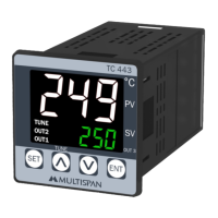
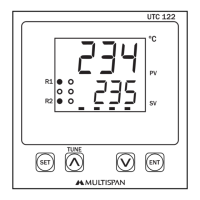
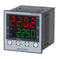
Describes the display characteristics and available keys.
Provides unit size and panel cutout dimensions.
Details PID control with Auto-Tuning and ON-OFF control.
Describes BL.TP (Blower Time Proportional) and ON-OFF control.
Specifies alarm types: Low, High, Absolute Low/Outband.
Details the number, type, and rating of relay outputs.
Indicates the status of control output 1.
Indicates the status of control output 2.
Indicates the status of control output 3.
Indicates when the auto-tuning function is active.
Shows delay time count status via blinking display point.
Describes how to enter parameter setting and auto-tuning.
Details actions like setting parameters and saving changes.
Emphasizes following manual and equipment safety instructions.
Highlights critical risk of electric shock during operation.
Advises on regular cleaning to avoid blockages.
Specifies using a soft cloth and avoiding certain cleaning agents.
States that fusible resistors should not be replaced by the operator.
Details precautions for wiring to prevent electric shock.
Provides guidance on using twisted wires for EMI reduction.
Specifies minimum cross-section and insulation for power cables.
Advises on using specific wires for thermocouple/RTD extensions.
Suggests using standard power supply cable for anti-noise effect.
Explains that terminals are inaccessible after installation.
Warns against metal debris entering the product during installation.
Mandates installing a circuit breaker for power ON/OFF.
Advises using and storing within specified environmental ranges.
Instructs to prepare the panel cutout with correct dimensions.
Describes fitting the unit into the panel using the clamp.
Warns against installing near heating sources or caustic vapors.
Specifies terminal size and tightening torque for wiring.
Advises not to connect anything to unused terminals.
Lists error codes like 'OPn' and 'SrE' with their meanings.
Provides steps to resolve sensor connection and other errors.
Explains how to apply factory set values using the ENT key.
Describes how to exit factory setting mode without applying changes.
Details the process of setting SP1, SP2, and SP3 values.
Lists control parameters like PB, IT, DT with their acceptable ranges.
Indicates the password required for basic configuration.
Defines settings for Heat + Cool mode.
Defines settings for Heat + Alarm mode.
Defines settings for Cool + Cool mode.
Defines settings for Cool + Alarm mode.
Indicates the password required for control parameter settings.
Details parameters for PID control action 1.
Details parameters for Blower TP control action 2.
Configuration steps when ON-OFF control is selected.
Configuration steps when PID control is selected.
Settings for relative input mode.
Settings for individual input mode.
Configuration steps when ON-OFF control is selected.
Configuration steps when PID control is selected.
Settings for relative input mode.
Settings for individual input mode.
Configuration for ALM2 based on High/AB-L/LOW selection.
Settings for relative input mode.
Settings for individual input mode.
Settings for relative input mode.
Settings for individual input mode.
Configuration for ALM2 based on High/AB-L/LOW selection.
Defines Set Point 1 for Output 1.
Defines Set Point 2 for Output 2.
Describes the Proportional Band parameter for PID action.
Explains the Integral Time Constant parameter.
Explains the Derivative Time Constant parameter.
Illustrates the ON-OFF control operation for heating.
Illustrates the ON-OFF control operation for cooling.
Explains the auto-tuning process and its benefits.
Details how to initiate or halt the PID auto-tuning process.
Illustrates the behavior of the low alarm function.
Illustrates the behavior of the high alarm function.
Illustrates the behavior of the inband alarm function.
Illustrates the behavior of the outband alarm function.
Illustrates the behavior of the absolute low alarm function.
Illustrates the behavior of the absolute outband alarm function.
This document describes the Multispan TC-443 Temperature Controller, a device designed for precise temperature management in various applications.
The TC-443 is a temperature controller that offers both heating and cooling control, along with alarm functionalities. It supports PID control with auto-tuning, as well as ON-OFF control for both heating and cooling. The device can manage up to three output relays for control and alarm functions. Its primary function is to monitor and maintain a set process value (PV) relative to a desired set value (SV) using a J-type sensor.
Power Supply:
Environmental Conditions:
Input Specification:
Display and Keys:
Dimensions:
Control Method:
Output Specification:
Key Operation:
Display Features:
Error Display:
Factory Setting:
Parameter Setting Modes:
Auto-Tuning Function:
Control Functions:
Alarm Operation:
Safety Precautions:
Mechanical Installation Guidelines:
General Maintenance:
| Brand | MULTISPAN |
|---|---|
| Model | TC-443 |
| Category | Temperature Controller |
| Language | English |