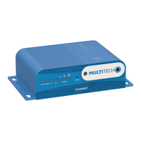
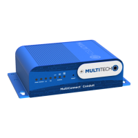
CONDUIT
®
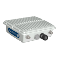
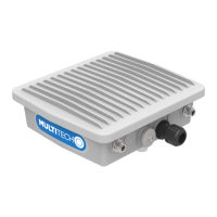
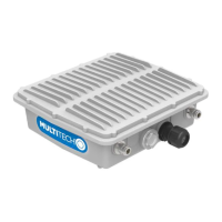
IP67 BASE STATION
6 Conduit
®
Base Station IP67 Getting Started Guide for Versions 1.5 and 2.1
V2.1 Features
V2.1 refers to the Semtech reference design; the previous reference design was V1.5.
Models MTCDTIP xxx266x-xxx and xxx-267x-xxx are V1.5.
Models MTCDTIP xxx270x-xxx and xxx-275x-xxx are V2.1.
The V2.1 hardware design differs from the previous V1.5 design in the following ways:
The custom, single purpose Semtech RF front-end ASIC was replaced by a popular wideband general
purpose single-chip RF front-end from Analog Devices – the AD9361. This change transitioned
Semtech's LoRa offering from a purely custom chipset to an SDR (Software-Defined Radio) architecture.
The Semtech SX1301 baseband processor chips were retained in the design, but now provide much
more limited functionality, essentially becoming hardware accelerator blocks whose purpose is to
detect and synchronize the preamble (fixed symbol sequence present at the start of every LoRa packet)
for incoming packets on multiple frequency slots with multiple spreading factors. This necessary
functionality (essentially multiple concurrent FFTs) was more economical in the original ASICs than in an
FPGA or a set of general-purpose DSPs.
Following a popular pattern for SDR architectures, a large FPGA (a lower-end, but still relatively large
Altera / Intel part) is at the center of the system, with all the other system components, including the
Analog Devices RF front-end, the Semtech SX1301 ASICs, and a set of TI OMAP-L138 ARM/DSP SoC chips
connected to it.
The DSP core of the TI SoCs are used for packet symbol detection, decoding, etc.
At system startup, the FPGA must first be configured from its associated SPI Flash memory device. The
same SPI flash device also contains code which will run on the TI DSPs. After the FPGA is configured, a
state machine within the FPGA reads this code from the Flash memory, loads it into the DSP memory
space, and starts the DSP.
The V2.1 design includes a GPS receiver module to provide timing synchronization between
geographically-dispersed gateways. The high-accuracy one-pulse-per-second (PPS) output from this
receiver module maintains an accurate internal 250 MHz (4 ns period) timing counter within the FPGA.
The GPS receiver and the associated high-speed counter were added specifically to enable a server-
layer application to estimate the physical location of a node based on the Time Difference-of-Arrival
(TDOA) of the same packet transmitted by the node at multiple (at least three) gateways. This TDOA
geolocation scheme works successfully, but accuracy is limited by topography and the number of
gateways providing timing information. Multi-path (reflected) signals constitute the primary challenge
for this scheme since they arrive at different times based on the different path lengths.
For this initial V2.1 release:
V2.1 hardware supports geolocation.
To get the fine timestamp for geolocation, you will need the AES keys. These can be obtained
from Semtech, which has licensed the geolocation resolver software.
Multitech supplies the chip ID that can be used by the network service providers for obtaining
the AES keys.
The packet format of the LoRa V2.1 is not backward-compatible with the LoRa V1.5 packet format. Therefore,
packet processing at the server layer (which sends/receive packets to/from LoRa gateways) fails for V2.1 packets if
the code has not been upgraded to handle them. Our MultiTech server code has not been upgraded yet, and
therefore cannot be used to process LoRa V2.1 packets. Therefore, if the customer does not have additional
server-layer support, the MultiTech LoRa V2.1 gateway can only be used as a packet forwarder. Also, unlike the