M120
4.7Reactivationairowadjustment
Estimatethepressuredropintheductsystemforreactivationandwetairaccordingtothefollowing:
■EachmetrelengthofØ80mmductgivesapressuredropof1.0Pa(0.1mmwg).
■Each90°or45°bendonanØ80mmductgivesapressuredropof1.0Pa(0.1mmwg)
■OutletØ80mm(possiblywithameshscreen)givesapressuredropof20.0Pa(2.0mmwg)
Ifthetotalpressuredropexceeds100Pa(10mmwg)theoriceplateintheinletshouldberemoved.
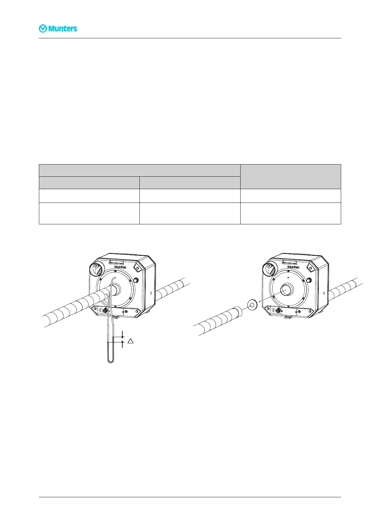
Indoubtfulcasesacheckmeasurementoftheairowshouldbemadeasfollows:
■Connectamanometertothepressuretappingpointforthereactivationair.Ifthedehumidieris
connectedtotheduct,aholeismadeintheductnearthedehumidiertoprovideaconnectionpointfor
themanometer,seeFigure4.8.
■ReadthepressuredroponthemanometerandfollowtheinstructionsinTable4.1.
Measuredpressuredrop
at50Hzat60Hz
Remarks
80-180Pa(8-18mmwg)160-280Pa(16-28mmwg)AllowedAirow
Lessthan80Pa(8mmwg)Lessthan160Pa(16mmwg)InsufcientAirow(REMOVE
ORIFICEPLATE)
Table4.1Pressuredropoveroriceplates
Figure4.8Measuringthepressuredrop
Manometer(eg.u-tube)OricePlate50Hzor60Hz
11Installation190TGB-1008-H1402