2203M4-JE-MY-iS2-N_2017.04.
Chapter 2 Compressor Specifications and Configuration
Screw Compressor i-series 2.5
Mechanisms
2-36
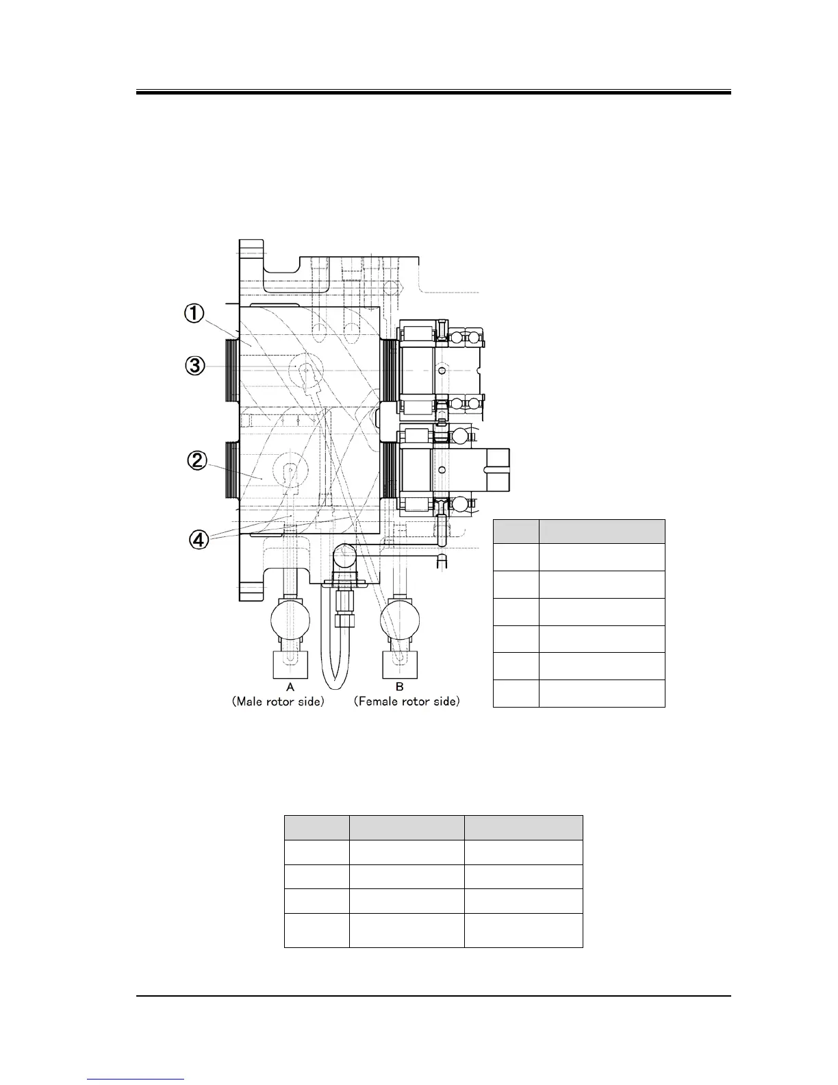
2.5.6 Capacity Control Mechanism
The capacity control of i-series compressor can be controlled in three steps of 50%, 75% and 100% via
the unloader piston installed at each male rotor side and female rotor side in the main rotor casing.
Each unloader piston controlled by solenoid valve.
Figure 2-28 Capacity Control Mechanism
Table 2-6 Control of Solenoid Valves for Capacity Control
A B
100% ON (Opened) ON (Opened)
75% OFF (Closed) ON (Closed)
50% OFF (Closed) OFF (Closed)