9
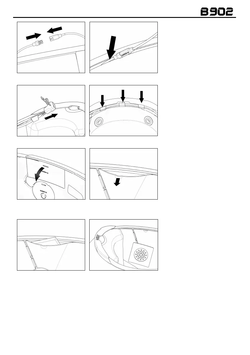
Fig. 20
Fig. 21
•
Hook up the microphone to
the connector coming o
the e-Box (Fig. 20).
•
Position the wiring and the
connectors behind the cheek
pad lining, lifting it with the
help of a flat head tool (Fig.
21).
Fig. 22
Fig. 23
•
found on the comfort padding
(Fig. 22).
•
Position the wiring and the
antenna in the rear part of the
helmet (Fig. 23).
Fig. 24 A – X-1005 HELMET
Fig. 24 B – X-903 HELMET
•
helmet, bend the cheek pad
lining and insert the battery in
its housing (Fig. 24 A/B - 25).
ONLY FOR X-1005 HELMETS
R
emove the filling material.
Keep it in case you want to
use the helmet without the N-
Com system install
future.
Fig. 25
Fig. 26
•
Position the right loudspeaker
in its housing, inserting the
cable in the special groo
(Fig. 26). If necessary, secure
adhesive supplied as standard
equipment.
• Position the wiring and the connectors behind the cheek pad lining, lifting it up with the help of a
flat head tool.
3.4.
Repositioning the padding
Reposition the internal comfort padding by following the specific instructions provided in the helmet
user manual.
Warning:
Always verify the proper length of your chinstrap and adjust it if necessary, referring to the
specific helmet instructions.
 Loading...