For Sales and Support, Contact Walker EMD • www.walkeremd.com • Toll-free: (800) 876-4444 • Tel: (203) 426-7700 • Fax: (203) 426-7800
(Revised 2011-11-15) Page 11 of 169
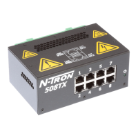
NOTE: The RJ45 data port has two LEDs located on each connector. The left LED indicates LINK status,
and the right LED indicates ACTIVITY.
LEDs: The table below describes the operating modes:
Power is ON and a fault condition exists
10/100/1000Mb Link between ports
Data is active between ports
Data is inactive between ports
APPLYING POWER AND FAULT CONNECTIONS (Back View)
7026TX with DC Power Supply Installed
Unscrew & Remove the DC Voltage Input
Plug from the Power Input Header
Install the DC Power Cables into the Plug
(observing polarity).
Plug the Voltage Input Plug back into the
Power Input Header.
Tightening torque for the terminal block
power plug is 0.5 Nm/0.368 Pound Foot.
Verify the Power LED stays ON.
Notes:
When a DC Power supply is installed, only one power supply must be connected to power for
minimal operation. For redundant power operation, V
1
and V
2
inputs must be connected to separate
DC Voltage sources. This device will draw current from both sources simultaneously. Use 16-28
gauge wire when connecting to the power supply.
Recommended 24V DC Power Supplies, similar to: N-Tron‘s P/N NTPS-24-1.3

 Loading...