ElectricalInstallaonManualU-30“D”Control www.NabcoEntrances.com
Part #C-00121 Rev. 8-25-16
2-8 GengStarted
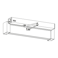
Figure 2-1
DN 0537
Power Supply
U30 Microprocessor Controller
Operator
Header
>
P
O
M
<
0
7
1
2
3
4
5
6
7
8
9
1
0
1
1
12
G
Y
R
O
T
E
C
H
D
S
-
1
5
0
N
A
(
2
4
-
11
3
2
7
)
M
A
D
E
I
N
J
A
PA
N
12
13
14
15
16
Sequential Activation
SQ
Auxiliary Output (Open-Collector)
OUT
5Amax.(0-20V), 3.2Amax.(20-30V)
30V(42.4Vpeak)max.
Contact Output (Class2 Load only)
Common
N/C
N/O
OUT.A
OUT.B
OUT.C
12VDC-(Common)
7
FUNCTION [SLIDING DOOR]
SYMBOL
No.
Reduced Opening Switch
11
10
9
8
7
6
5
4
3
2
1
Breakout Detector
Sidelite Presence Sensor
Exterior Activation
BA
62
SLS
M1
H
M0
Holding Beam
Interior Activation
12VDC-(Common)
12VDC+
6B
9DC12V
7
61
Mode Switch (see Mode SW Usage shown left)
HANDY TERMINAL・6P
RELATED DEVICES・16P
To protect against risk of fire
or electric shock,use only the
certified NABCO power supply.
WARNING
No.
MOTOR・12P
ERROR
POWER
BA
62
H
6B
61
INDICATORS
POWER・2P
Do not disassemble the control box.
There are no user serviceable parts
inside.
To maintain warranty,repairs must be
made by authorized NABCO facilities.
CAUTION
Adjustments to the door can only be made
with the NABCO Handy Terminal.
Mode SW Usage
Gnd
GndGnd
Open
Open
Open
Gnd
Open
M0
M1
MODE
TWO WAY
ONE WAY
NIGHT
HOLD OPEN
GYRO TECH
248901-
Microprocessor Controller
20VAC 50/60Hz
TRANSFORMER
LABEL
A
M
P
5
I
O
TB1
NOISE
FILTER
TB2
T1
S1
Z
N
R
2
Z
N
R
1
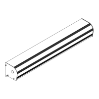
DN 0536
Power Supply
U30 Microprocessor Controller
Operator
Header
TRANSFORMER
LABEL
A
M
P
5
I
O
TB1
NOISE
FILTER
TB2
T1
S1
Z
N
R
2
Z
N
R
1
>
P
O
M
<
0
7
1
2
3
4
5
6
7
8
9
1
0
1
1
12
G
Y
R
O
T
E
C
H
D
S
-
1
5
0
N
A
(2
4
-
11
3
2
7
)
M
A
D
E
I
N
J
A
P
A
N
12
13
14
15
16
Sequential Activation
SQ
Auxiliary Output (Open-Collector)
OUT
5Amax.(0-20V), 3.2Amax.(20-30V)
30V(42.4Vpeak)max.
Contact Output (Class2 Load only)
Common
N/C
N/O
OUT.A
OUT.B
OUT.C
12VDC-(Common)
7
FUNCTION [SLIDING DOOR]
SYMBOL
No.
Reduced Opening Switch
11
10
9
8
7
6
5
4
3
2
1
Breakout Detector
Sidelite Presence Sensor
Exterior Activation
BA
62
SLS
M1
H
M0
Holding Beam
Interior Activation
12VDC-(Common)
12VDC+
6B
9DC12V
7
61
Mode Switch (see Mode SW Usage shown left)
HANDY TERMINAL・6P
RELATED DEVICES・16P
To protect against risk of fire
or electric shock,use only the
certified NABCO power supply.
WARNING
No.
MOTOR・12P
ERROR
POWER
BA
62
H
6B
61
INDICATORS
POWER・2P
Do not disassemble the control box.
There are no user serviceable parts
inside.
To maintain warranty,repairs must be
made by authorized NABCO facilities.
CAUTION
Adjustments to the door can only be made
with the NABCO Handy Terminal.
Mode SW Usage
Gnd
GndGnd
Open
Open
Open
Gnd
Open
M0
M1
MODE
TWO WAY
ONE WAY
NIGHT
HOLD OPEN
GYRO TECH
248901-
Microprocessor Controller
20VAC 50/60Hz
TRANSFORMER
LAB
E
L
A
M
P
5
I
O
TB1
NOISE
FILTER
TB2
T1
S1
Z
N
R
2
Z
N
R
1
12
13
14
15
16
Sequential Activation
SQ
Auxiliary Output (Open-Collector)
OUT
5Amax.(0-20V), 3.2Amax.(20-30V)
30V(42.4Vpeak)max.
Contact Output (Class2 Load only)
Common
N/C
N/O
OUT.A
OUT.B
OUT.C
12VDC-(Common)
7
FUNCTION [SLIDING DOOR]
SYMBOL
No.
Reduced Opening Switch
11
10
9
8
7
6
5
4
3
2
1
Breakout Detector
Sidelite Presence Sensor
Exterior Activation
BA
62
SLS
M1
H
M0
Holding Beam
Interior Activation
12VDC-(Common)
12VDC+
6B
9DC12V
7
61
Mode Switch (see Mode SW Usage shown left)
HANDY TERMINAL・6P
RELATED DEVICES・16P
To protect against risk of fire
or electric shock,use only the
certified NABCO power supply.
WARNING
No.
MOTOR・12P
ERROR
POWER
BA
62
H
6B
61
INDICATORS
POWE
R
・2P
Do not disassemble the control box.
There are no user serviceable parts
inside.
To maintain warranty,repairs must be
made by authorized NABCO facilities.
CAUTION
Adjustments to the door can only be made
with the NABCO Handy Terminal.
Mode SW Usage
Gnd
GndGnd
Open
Open
Open
Gnd
Open
M0
M1
MODE
TWO WAY
ONE WAY
NIGHT
HOLD OPEN
GYRO TECH
248901-
Microprocessor Controller
20VAC 50/60Hz
>
P
O
M
<
0
7
1
2
3
4
5
6
7
8
9
1
0
1
1
12
G
Y
R
O
T
E
C
H
D
S
-
1
5
0
N
A
(
2
4
-
1
13
2
7
)
M
A
D
E
I
N
J
A
P
A
N
NABCO
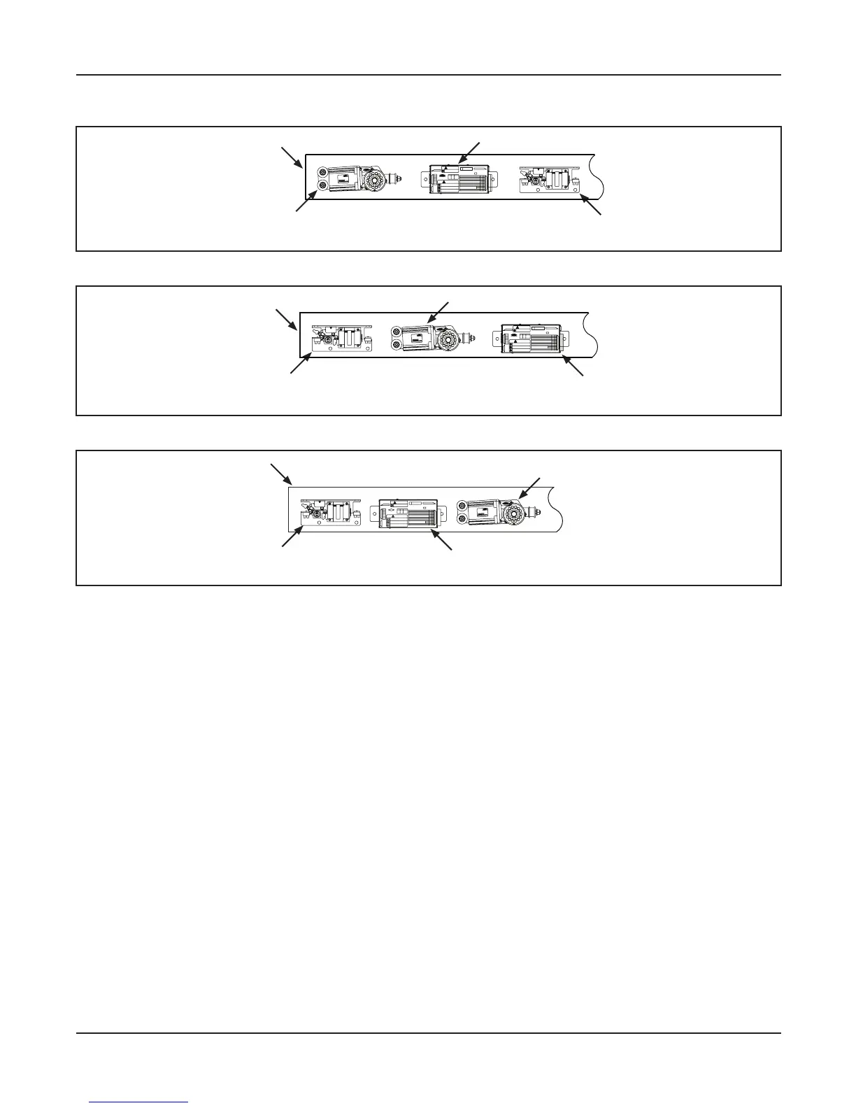
DN 0535
Power Supply
U30 Microprocessor Controller
Operator
Figure 2-2
Figure 2-3
 Loading...