Rev. 8-25-16 Part #C-00121
www.NabcoEntrances.com ElectricalInstallaonManualU-30“D”Control
ElectricLockWiring 7-23
►
•
►
•
Microprocessor Control when it receives a signal from a:
►
► Transmitter
► Activation Device on the face of the Door
need to be adjusted.
Close Door Panel(s).
secure to the Header.
a. Do not overtighten.
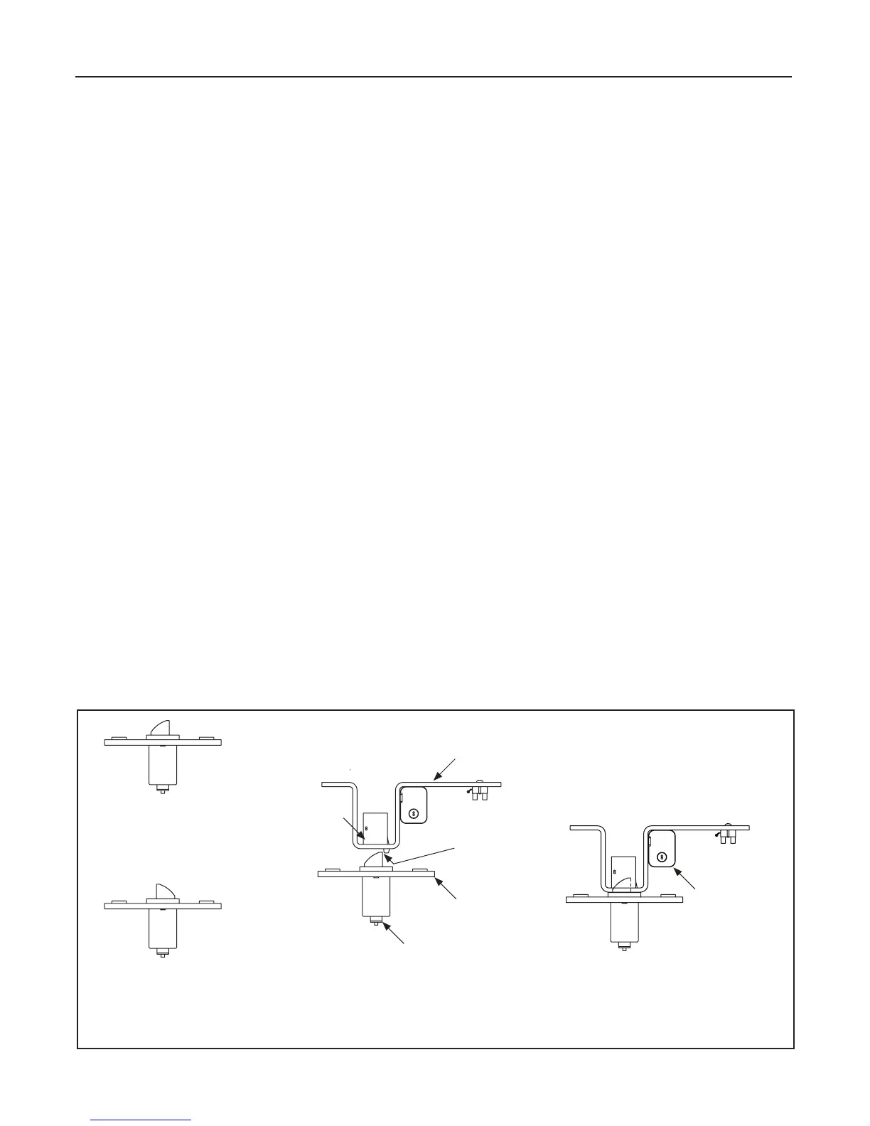
Figure 7-1
DN 1026
Electric Lock Assembly
LATCHBOLT POSITION:
• BIPART UNITS
• LH SINGLE F.O.
• RH SINGLE F.S.
LATCHBOLT POSITION:
• RH SINGLE F.O.
• LH SINGLE F.S.
Dead Bolt Assembly
Belt Clip
Electric Strike
Dead Bolt Engaged with Electric Strike
(Door in Full Closed Posi on)
Slight Gap
(Between Strike Wall
and Dead Bolt)
Terminal Strip
(Strike Side of Door)
 Loading...