Rev. 8-25-16 Part #C-00121
www.NabcoEntrances.com ElectricalInstallaonManualU-30“D”Control
ConnectIncoming120VACWires 3-9
Disconnect power to the junction box prior to making any electrical connections.
Failure to do so may result in serious personal or fatal injury. When uncertain
whether power supply is disconnected, always verify using a voltmeter.
Notice: Wiring must meet all local, state, federal or other governing agency codes.
Ensure all power is disconnected at the Junction box.
Electric Service Access Hole located at the left or right side of Jamb Tube and Header End Cap.
a.
Electrical Conduit.
Keep all Incoming 120 VAC wiring separate from low voltage wiring within Header.
Do Not route 120 VAC wires near the U30 Microprocessor Controller and Operater.
Please see
Power Supply.
Read and understand the “U30 Controller Setup and Programming Manual”
P/N 15-9000 before attempting to power-up the GT-1175 Slide Door. Failure to do
so may result in damage to the Slide door and/or injury to the installer and will
nullify all warranties.
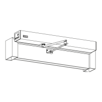
Figure 3-1
AC 115V ± 10%
50 / 60 Hz
Ground Wire
Auxiliary 120 VAC Power wires
(These wires normally coiled and ed up)
On/Off
Power Switch
DN 0647
U30 Microprocessor Control
P/N V-00020
0
7
1
2
3
4
5
6
7
8
9
1
0
1
1
12
>
P
O
M
<
N
AB
CO
GY
R
O TEC H
DS
-1
5
00
D
2
4-
1
1
3
2
7
0
Na
bt
es
c
o C
orp
o
r
at
io
n
M
AD
EI N
J
A
P
A
N
N
A
B
CO
N
A
B
CO
CAUTION
!
RELATED DEVICES・16P
12
13
14
15
16
No.
11
10
9
8
7
6
5
4
3
2
1
SYMBOL
H
M0
9DC12V
SQ
OUT
Common
N/C
N/O
OUT.A
OUT.B
OUT.C
7
BA
62
SLS
M1
6B
7
61
Sequential Activation
Auxiliary Output (Open-Collector)
5Amax.(0-20V), 3.2Amax.(20-30V)
30V(42.4Vpeak)max.
Contact Output (Class2 Load only)
12VDC-(Common)
FUNCTION [SLIDING DOOR]
Reduced Opening Switch
Breakout Detector
Sidelite Presence Sensor
Exterior Activation
Holding Beam
Interior Activation
12VDC-(Common)
12VDC+
Mode Switch (see Mode SW Usage shown left)
HANDY TERMINAL・6P
No.
248901-
Microprocessor Controller
Mode SW Usage
Gnd
GndGnd
Open
Open
Open
Gnd
Open
M0
M1
MODE
TWO WAY
ONE WAY
NIGHT
HOLD OPEN
To protect against risk of fire
or electric shock,use only the
certified NABCO power supply.
WARNING
MOTOR・12P
ERROR
POWER
BA
62
H
6B
61
INDICATORS
POWER・2P
Do not disassemble the control box.
There are no user serviceable parts
inside.
To maintain warranty,repairs must be
made by authorized NABCO facilities.
Adjustments to the door can only be made
with the NABCO Handy Terminal.
20VAC 50/60Hz
GYRO TECH
NABC O
!
!
!
!
TB1
NOISE
FILTER
TB2
T1
S1
PE
N
L
LOAD
-CIRCUIT-
-BREAKER-
RED INDICATES
POWER IS OFF
PRESS
TO
RESET
POWER SUPPLY
ASSEMBLY
P/N 9418800100
NABCO
14-11741
ENTRANCES, INC.
Power Supply
P/N V-00029
Motor/Operator
P/N M-00395
120 VAC
 Loading...