19 of 53
www.NabcoEntrances.com GT1175 (H105 Medium) Hurricane Quick Set-Up and Parts Guide
Rev 8-10-16 P/N C-00106
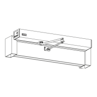
6. Check for door sag.
7. Go to the Preload Block located inside Top Rail.
8. Loosen (2) Locking Bolts.
9. Go to the back edge of Pivot Sle. Reduce Door sag by ghtening the 5/16 inch Adjustment Set Screw with an 5/32 inch Allen
Wrench.
a. The Door should latch without having to be manually lied.
b. Do Not allow the Adjusng Set Screw to protrude more than 5/32 inch past the end of sle.
c. If deemed necessary: an oponal 1/2 inch Set Screw has been provided by NABCO.
Figure 35 Adjust the Preload
DN 0727
Preload Block
5/16” Adjustment Set Screw
(If needed: use op onal 1/2” Set
Screw provided by NABCO)
Locking Bolts
Limit Arm
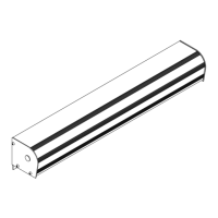
If Preload results in a misalignment of the Strike end of the door and Carrier; connue with the following instrucons.
1. Loosen the Allen head fasteners in the pivot bar and slide the pivot bar in the hanger unl the door and hanger are
properly aligned.
2. Verify that the panic catch in the top rail of the door and the hanger are sll aligned.
3. If necessary loosen the set screws for the panic catch in the hanger and reposion to align with the panic catch in the top rail.
Figure 36 Correct Preload Misalignment
DN 0741
Misaligned
Carrier and Door
Misaligned a er
adjus ng preload
1/4-20 x 1-3/4”
Hex Screw
Pivot
Carrier
5/16-24 x 1/2”
Set Screw
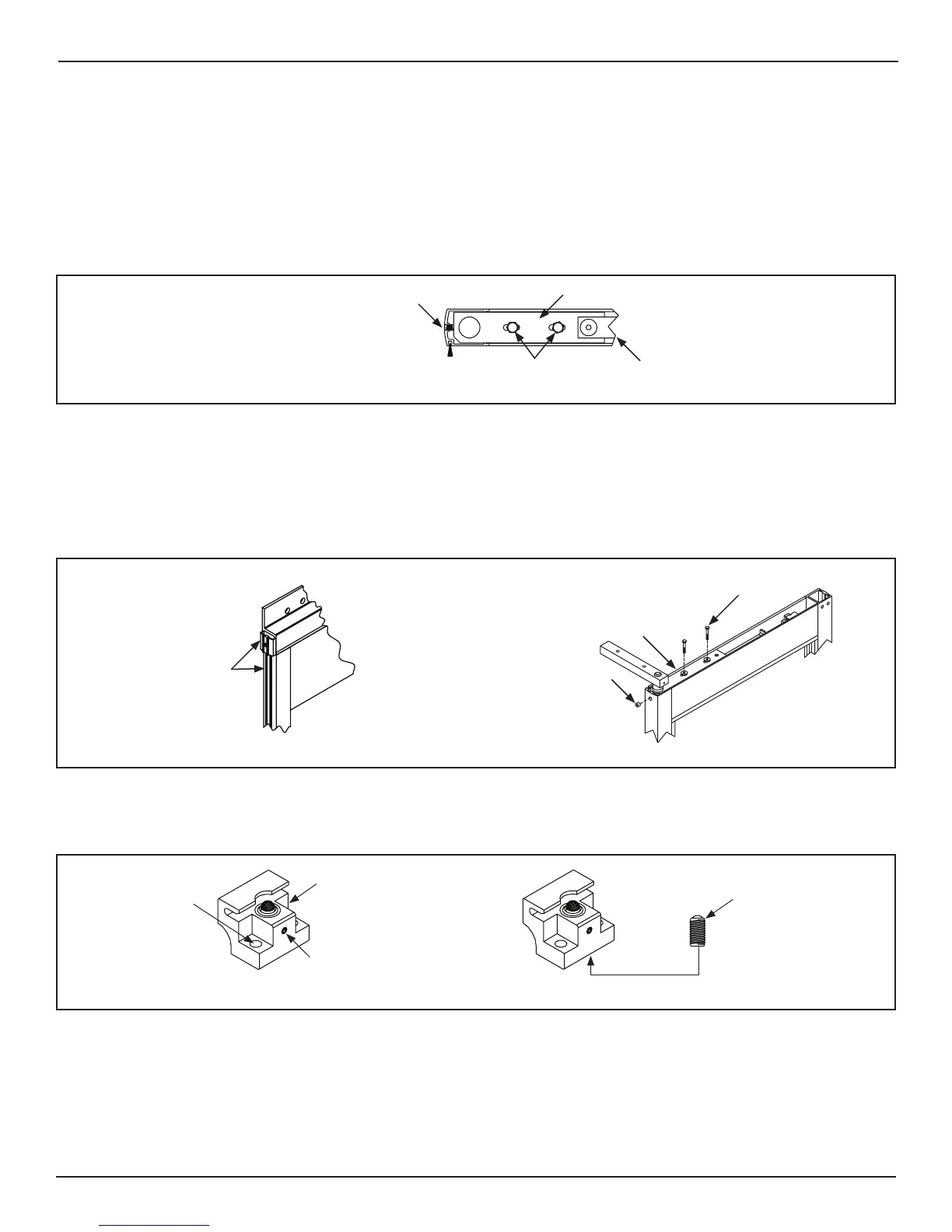
1. Breakout the Slide door.
2. Remove (2) 1/4-20 x 1-1/4 inch Socket screws that are used to secure the Allen Block to the Top Rail.
Ball Plunger
Loosen the Set Screw
Panic Catch
DN 0122
1/4-20 x 1-1/4”
Socket Screw
Figure 37 Panic Adjustment
3. Loosen the Set screw that is located in front of the Panic Block.
a. Adjust the Ball plunger down, so Panic Catch does not engage if Panic Hardware is used.
4. Raise or lower the Ball plunger located underneath the Panic Block. Tighten the Set screw.
a. The Ball plunger must be adjusted for proper breakout resistance to meet ANSI A156.10 code or local code.
5. Reinstall the Panic Block and ghten the two Allen screws that were saved for reinstallaon. Repeat if necessary.
 Loading...