12 of 53
GT1175 (H105 Medium) Hurricane Quick Set-Up and Parts Guide www.NabcoEntrances.com
P/N C-00106 Rev 8-10-16
Figure 16 Slide Bottom Guide Assembly into Bottom Rail
DN 1022
Double Roller
Strike S le
BREAKOUT SIDE
1. Insert the Threshold Bracket into the Boom Rail so the plate poron with (2) screw holes scks out from underneath in
direcon of where the Slide door is to be installed.
2. Ensure the Fixed Panel is sll parallel to the chalk line so it remains square.
3. Secure the Threshold Bracket to the Strike Sle with (1) 1/4-20 x 5/8 inch Socket Head screw.
4. Secure the Cover Plate back onto the Strike Sle with (2) 1/4-20 x 5/8 inch Socket Head screws.
Figure 17 Install the Threshold Bracket
DN 1023
Threshold Bracket
Strike S le
1/4-20 x 5/8”
Socket Head Screw
1/4-20 x 5/8”
Socket Head Screw
FOR FIXED SIDELITE UNITS SKIP TO
SECTION 6
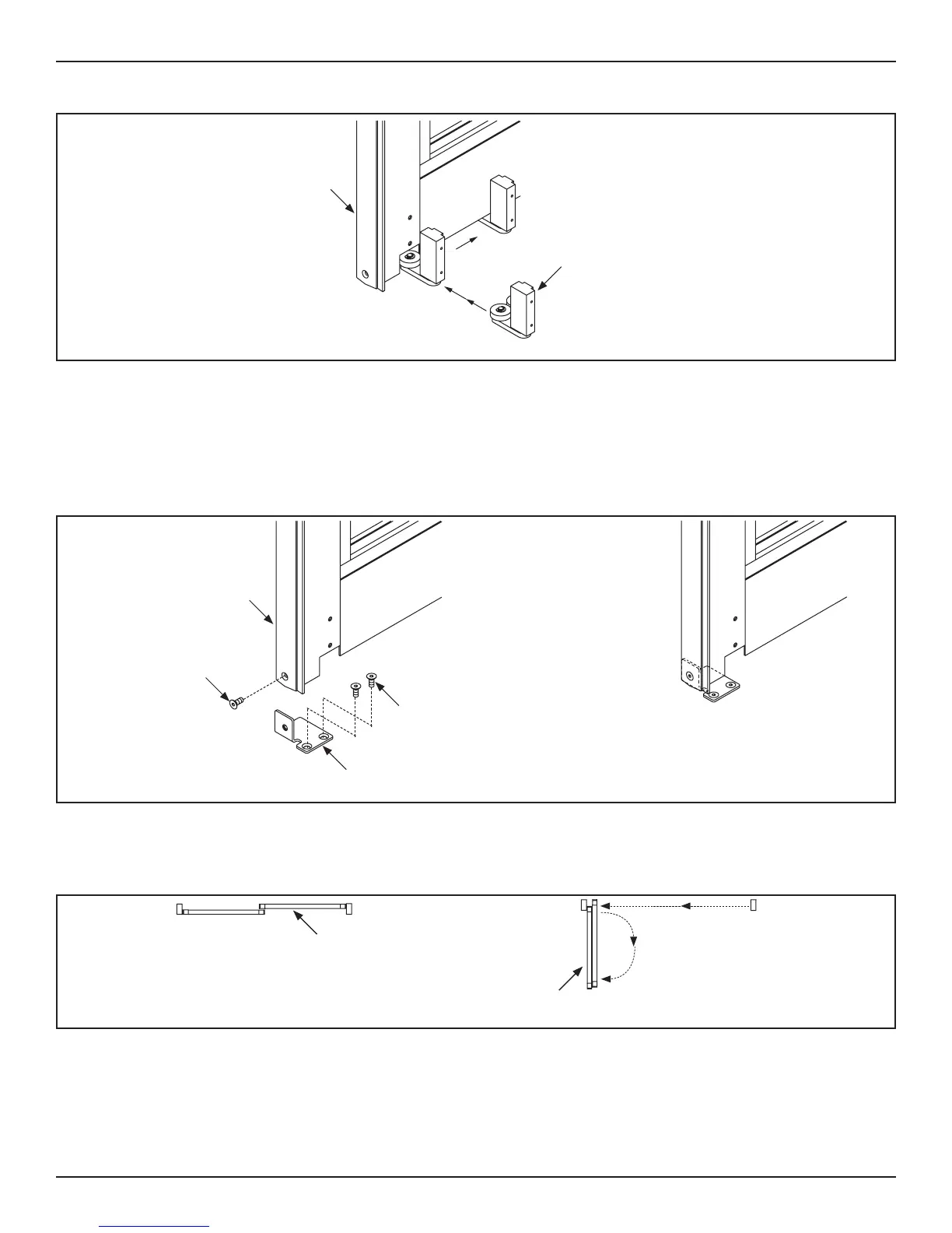
DN 0818
Slide Door
Swing Sidelite
Figure 18 Full Open Breakout
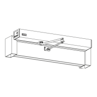
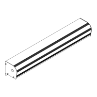
1. Obtain (1) Floor Pivot, (1) 1/4-20 x 1 inch Phillips Head screw, (1) 1/4 X 2-3/4 inch Flathead Tap Con, and (1) Bushing.
2. Insert the Floor Pivot into the hole located at the boom of the Pivot Jamb Tube.
a. The inseron end of the Floor Pivot is notched at both sides. It will be necessary to lt the Floor Pivot to interlock the
notched sides with the Jamb Tube.
 Loading...