10 of 53
GT1175 (H105 Medium) Hurricane Quick Set-Up and Parts Guide www.NabcoEntrances.com
P/N C-00106 Rev 8-10-16
DN 1017
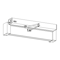
Plumb Line + 1/8” to edge of Track
Header Cover
1/8”
4.5”
NONBREAKOUT SIDE
Figure 10 Plumb Line
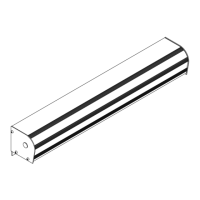
Slide Door
Fixed Sidelite
DN 0842
Figure 11 Fixed Sidelite, No Breakout
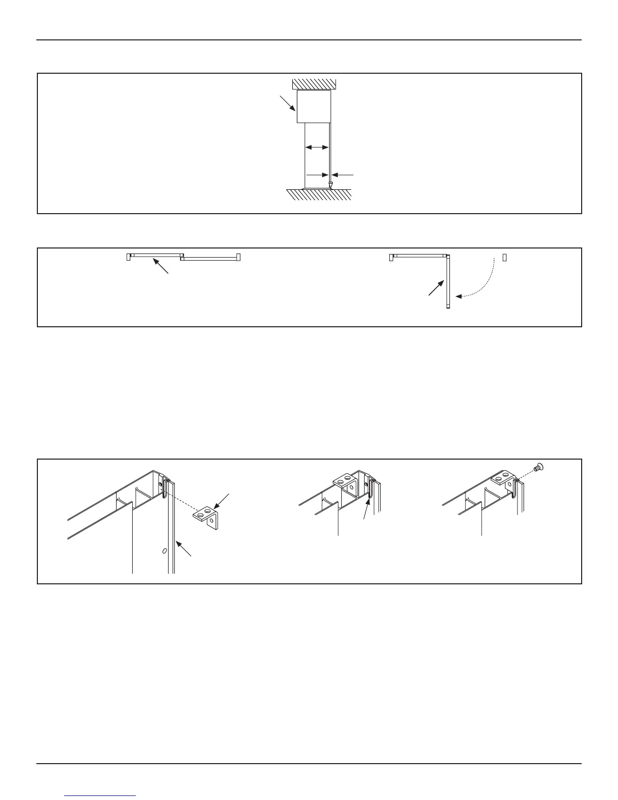
1. Obtain (1) 1/4-20 x 1/2 inch Flat Head Screws provided by NABCO.
2. Go to the Strike Sle located on the Strike side of the Fixed Sidelite.
3. Locate the Cut Out at the Top.
4. Locate (1) Mounng Bracket that was preinstalled under the Boom Lip of Header.
5. Li and then angle the Fixed Sidelite unl the Mounng Bracket is seated inside the Cut Out.
a. There is room inside the Strike Sle for the Mounng Bracket to move around within.
b. Move the Fixed Sidelite forward so the Pivot Sle does not scrape up against the (3) Mounng Brackets that were
preinstalled on the Pivot Jamb Tube.
Figure 12 Slide Mounting Bracket into Cut Out
DN 1019
Moun ng
Bracket
Strike S le
Cut Out
6. Locate (3) Cut Outs on the side of the Pivot Jamb Tube.
7. Align and then slide the Fixed Sidelite unl (3) Mounng Brackets are seated inside each Cut Out.
8. Connue to slide the Fixed Sidelite towards the Interior of the Building unl both Mounng Brackets bu up against the
inside wall of the Pivot Sle.
9. Align all (4) Mounng Bracket screw holes with the Pivot Sle screw holes and the Strike Sle screw hole.
10. Secure (3) Mounng Brackets located on the Pivot Jamb Tube to the Fixed Sidelite with (3) 1/4-20 x 7/16 inch Phillips
Head screws.
11. Secure (1) Mounng Bracket located under the Boom Lip of Header with (1) 1/4-20 x 1/2 inch Flat Head Screw.
 Loading...