Rev. 10-7-16 Part #C-00140
www.NabcoEntrances.com GT20 Control Wiring and Programming Manual
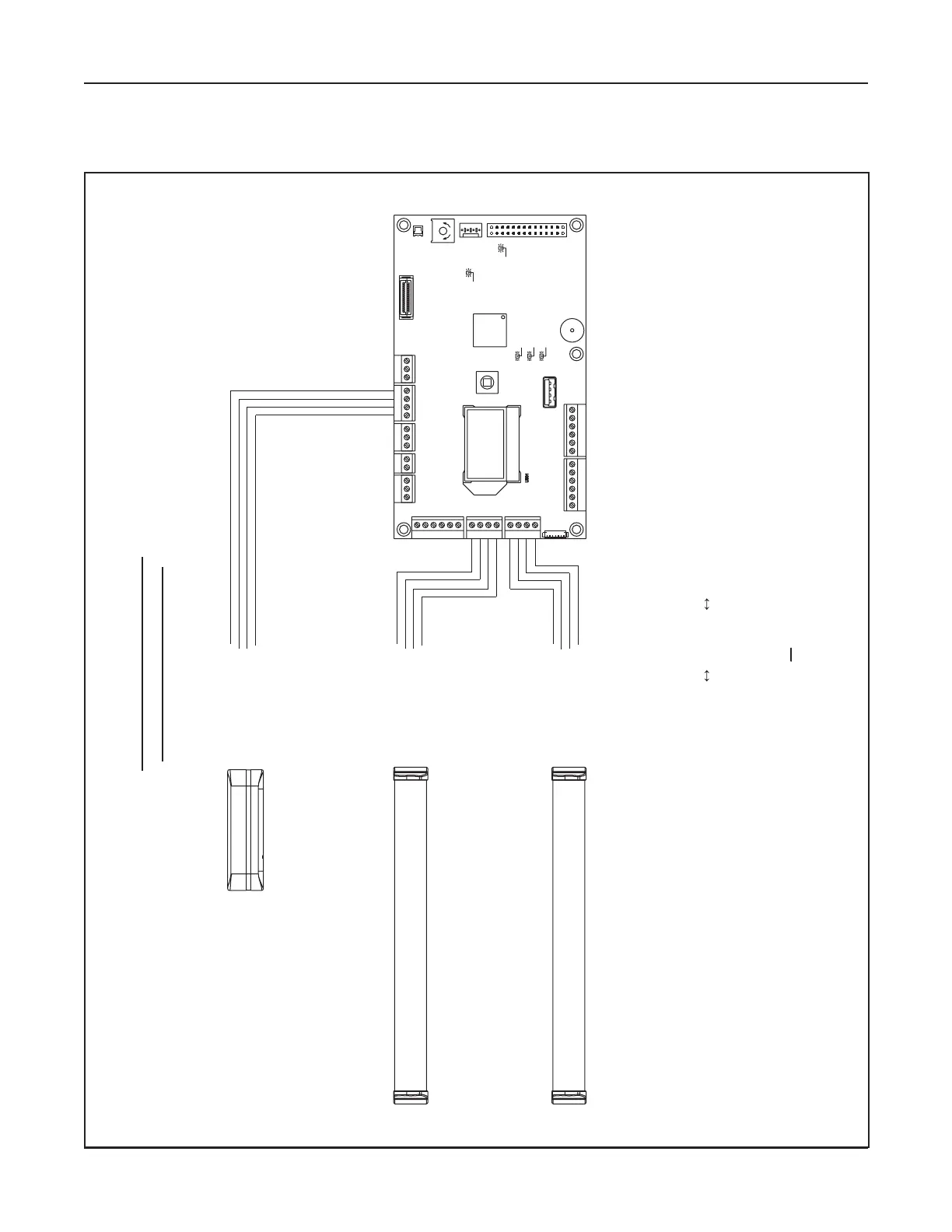
General Wiring 5-11
DN 1262
SA SL SO SM SW
X110 X108
27 28 29 30 31
18 19 20 21
X107
14 15 16 17
X105
10 11 12 13
8 9
X101
X112
54 31 2
X104 X102
X118
X103
X113
R552
X109
S501
X114
X116
30V OK
OE active (Opening element)
System OK
SE active (Safety element)
gn
bl
ge
5V OK
max. min.
32
gn
gn
PGPOPIPU
CG CHCL
X117
SG
X111
BG BUBD
14
15
17
18
19
21
COM
N.C.
PWR+
PWR-
COM
N.C.
PWR+
PWR-
Swing-Side
Door Mounted
Sensor
Approach-Side
Door Mounted
Sensor
WARNING!
When Any Safety Sensor Input is not Used,
A Jumper Must Be In Place At Input Terminals
15
16, and 19 20.
Swing-Side
Overhead
Presence Sensor
COM
N.C.
PWR+
PWR-
WARNING!
Total Power Consumption Of All
Sensors And Powered Activation
Devices Must Not Exceed 1.2 Amps.
PG
PO
16
20
PIPU
All Safety Sensors Must Use
Normally Closed Contacts
 Loading...