Do you have a question about the NAD C 320BEE and is the answer not in the manual?
Essential safety measures to prevent fire and electrical shock during servicing operations.
Explains the meaning of important warning symbols found in the manual.
Guidance for ensuring safe and optimal installation of the audio equipment.
Fundamental safety checks and practices to follow before and during servicing.
Procedure for testing the electrical insulation integrity of the unit.
Techniques for safely handling sensitive electronic components to prevent damage.
Detailed technical specifications for the power amplifier section in stereo mode.
Technical details for all line-level audio inputs.
Technical details for all line-level audio outputs.
Information on Treble and Bass control ranges.
Specifications related to the IR receiver and transmitter functions.
Technical details for the trigger output functionality.
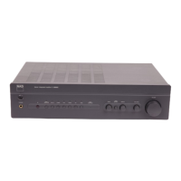
Provides the unit's physical dimensions and weight.
Procedures for setting output offset voltage and idling current without load.
Repeating initial calibration steps to ensure optimal performance.
Visual illustration of component placement for assembly and repair.
Lists diodes, transistors, integrated circuits, crystals, and capacitors.
Lists various types of capacitors and resistors with their specifications.
Detailed listing of resistors by type, value, and tolerance.
Lists inductors, connectors, cables, and relays used in the unit.
Lists switches, fuses, transformers, and printed circuit boards.
Lists hardware, mechanical parts, packing materials, and accessories.
| Input Sensitivity | 200 mV |
|---|---|
| Weight | 6.9 kg |
| Power Output | 50 W per channel into 8 ohms |
| Signal to Noise Ratio | 100 dB |
| Frequency Response | 20Hz - 20kHz (±0.3dB) |
| Dimensions | 435 x 100 x 290 mm |
| Input Impedance | 20 kOhms |