S
stephensdavidAug 1, 2025
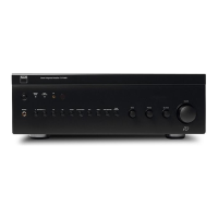
Why is there no sound coming from my NAD C 375BEE Amplifier?
- JJonathan BoyerAug 1, 2025
There are several reasons why your NAD Amplifier might not be producing sound: * The AC power lead might be unplugged, or the power might not be switched on. Ensure the AC lead is properly plugged in and the power is switched ON. * The Tape Monitor mode might be selected. De-select Tape Monitor mode. * The Mute function might be activated. Switch off Mute. * The rear Pre-out/Main-in amp links might not be fitted. Fit the links.