Do you have a question about the NAD C 325BEE and is the answer not in the manual?
Covers safety precautions for fire, shock hazards, and proper installation practices.
Outlines essential safety checks and general servicing guidelines for user safety.
Details general servicing procedures, contact cleaning, and insulation resistance testing.
Provides guidelines for safely handling electrostatically sensitive components.
Identifies and describes all rear panel input and output connectors.
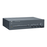
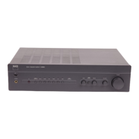
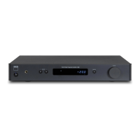
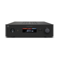
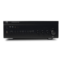
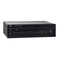
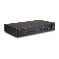
Lists and describes the functions of all front panel controls and indicators.
Details specifications for the power amplifier section, including output power and distortion.
Covers preamplifier section specifications, control ranges, and IR/trigger functions.
Provides physical dimensions and weight information for the unit.
Details the initial calibration steps for volume, idling current, and ISC circuit.
Describes the final tuning and calibration procedures after initial adjustments.
Shows detailed circuit schematics for amplifier sections and protection circuits.
Presents circuit diagrams for various interface boards like IR, iPod, Standby, and Key.
Details the circuit diagrams for the power supply unit.
Shows PCB layouts for the power board and the input/output module boards.
Displays PCB layouts for key, standby, iPod, IR, and headphone interface boards.
Presents PCB layouts for the surface-mount device (SMD) amplifier modules.
| Signal-to-Noise Ratio | >95dB |
|---|---|
| Input Sensitivity | 200 mV |
| Damping Factor | > 100 |
| Power Output | 50 W per channel into 8 ohms |
| Total Harmonic Distortion (THD) | < 0.03% |
| Input Impedance | 47 k ohms |
| Dimensions (metric) | 435 x 100 x 290 mm |