SETUP
ASSEMBLY AND INSTALLATION
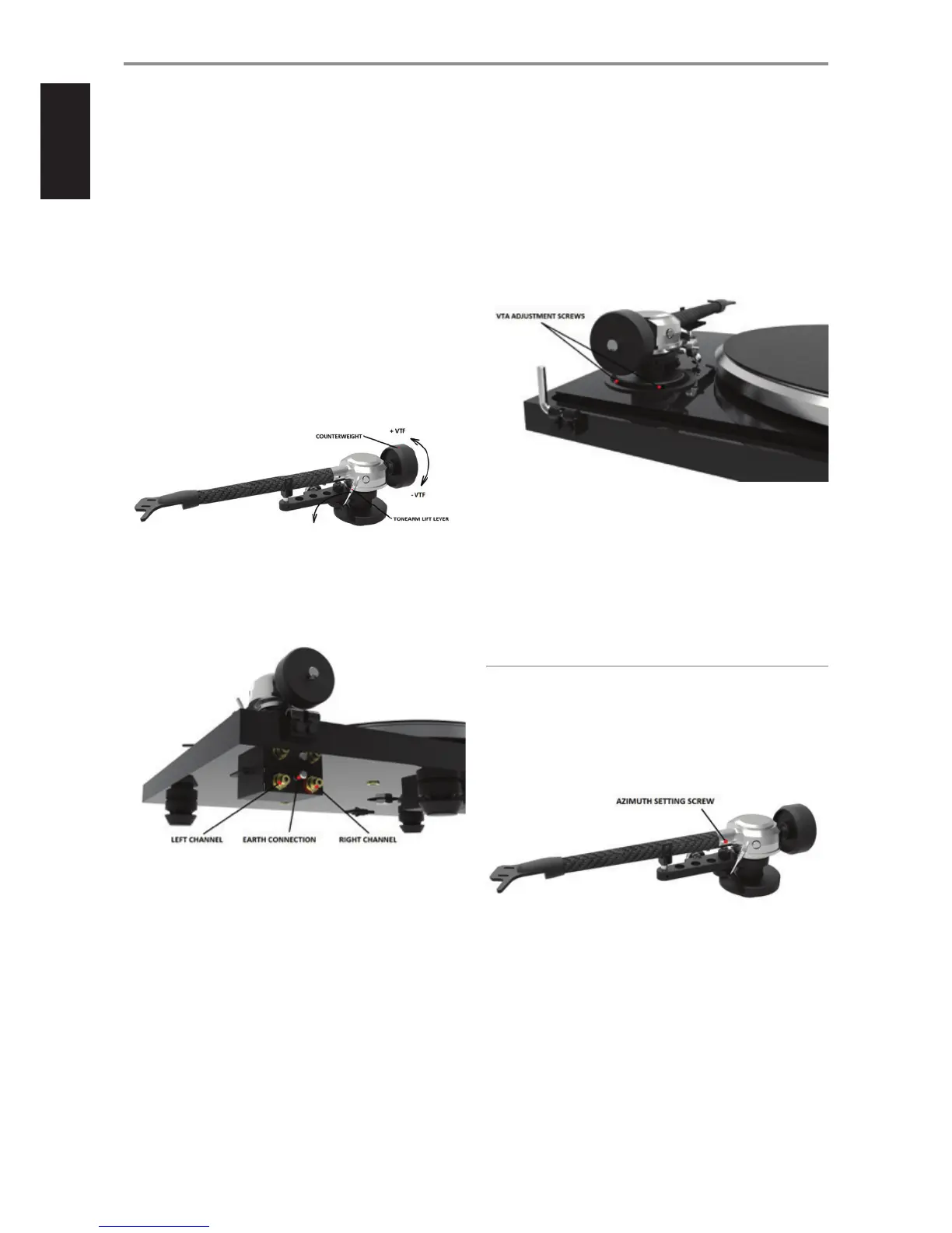
3 VERTICAL TRACKING FORCE SETTING (VTF)
Before setting the Vertical Tracking Force, conrm the exact weight
of your cartridge. Depending on your cartridge weight, determine
whether to use the counterweight with or without the additional insert,
in accordance with the specications above.
Pushing carefully, turn the counterweight onto the rear end of the
counterweight support rod as shown in the illustration below. Place
the stylus pressure gauge (not supplied) onto the platter. To set the
required VTF, lower the tonearm lift lever as indicated in the illustration
and place the tip of the stylus on the pressure gauge.
As viewed from the headshell, turning the counterweight
counterclockwise (moving it in closer toward the tonearm) increases
the VTF, turning clockwise (away from the tonearm) reduces the
VTF. Turn the counterweight appropriately until the VTF shown on
the pressure gauge matches your cartridge’s recommended vertical
tracking force specications.
4 TONEARM OUTPUT CONNECTION
Connect the tonearm cable provided with the accessories to the RCA
tonearm output that is located at the rear of the turntable, behind the
tonearm. Connect the grounding cable on the earth connection screw.
5 VERTICAL TRACKING ANGLE SETTING (VTA)
To set the Vertical Tracking Angle, rst put a record on the platter. When
the needle is lowered into the record groove, the tube of the tonearm
should be parallel to the surface of the record. If it is not, loosen both
hexagonal screws in the tonearm base just enough to allow vertical
movement of the arm pillar without force, and slide the arm up or
down until it is parallel.
Carefully and evenly retighten the hexagon screws without applying
excessive force (which could deform the arm pillar).
6 AZIMUTH SETTING
The cartridge needle must be perpendicular to the record in order to
trace the groove wall modulations correctly.
The azimuth (angle) is precisely set by the factory. In the event that you
need to modify this setting, however, follow the instructions below.
Loosen the small AZIMUTH SET SCREW, again using the 1.5 mm
hexagonal key.
NOTE
DO NOT REMOVE THE AZIMUTH SET SCREW COMPLETELY!
Loosen the screw just enough to be able to gently rotate the arm tube
and set the azimuth to the correct position. The correct position can
be checked from the front view, preferably with the needle placed on a
mirror placed on the platter. Once the azimuth setting is correct, gently
re-tighten the AZIMUTH SETTING SCREW.
6